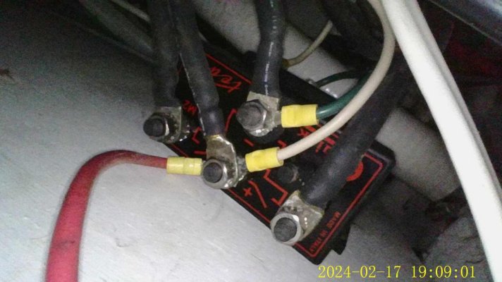
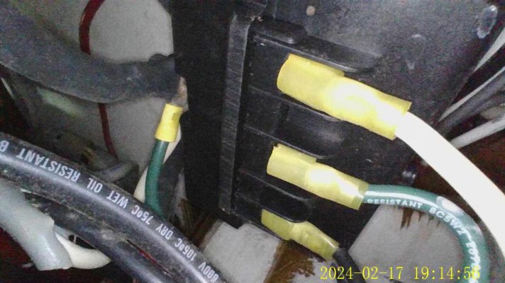
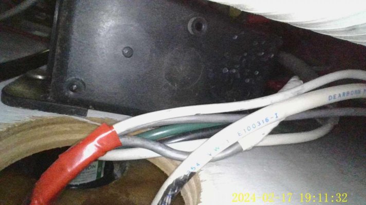
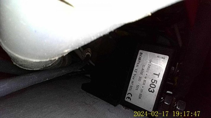
fuel diverter

The friendliest place on the web for anyone who enjoys boating.
If you have answers, please help by responding to the unanswered posts.
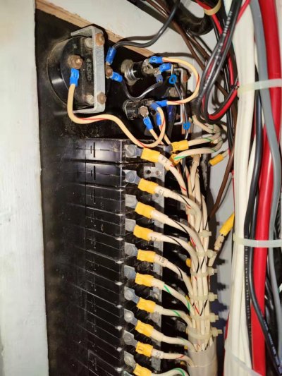
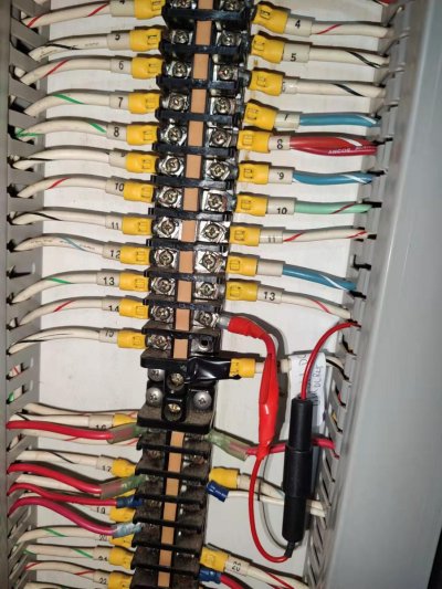
Tt has it correct. Make the change at the terminal strip, not on the circuit breaker. Leave the wire that comes from the breaker attached to the terminal strip, remove the one that goes to the fridge location. disconnect, insulate and tag the one you took off. Hide it inside the panduit in case you ever want to run dc power to the fridge again.
Run the new heater wires off the terminal strip where you fridge wire.
If you don’t know which wire is the one that comes from the breaker, just remove one wire from the terminal strip, turn the breaker off, then use your ohm meter to see which one it is. (That’s what I mean when I say to ring out the wire.)

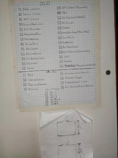
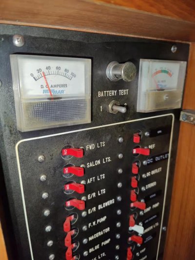
Remove line 15 from the terminal strip? Then turn off the ref breaker from the panel? Where do the two probes of the meter touch?
 
Last edited:
Remove line 15 from the terminal strip? Then turn off the ref breaker from the panel? Where do the two probes of the meter touch?

first turn the breaker off. verify that there's no power to terminal 15 on the terminal strip. remove one of the wires marked 15 from the terminal strip. use the ohm meter and put one test probe on the output side of the breaker. this is the wire marked 15 on the breaker. put the other probe on one of the wires at the terminal strip. when you find the wire that has zero ohms you have found the right wire. that would be the wire that remains connected on the terminal strip. insulate the other wire with tape or something and tag it so you know what it is for future use.
now you will have a wire connected from the breaker to the terminal strip and an empty slot to place your new positive wire for the heater. while you have your meter handy, after you have identified the wire from the breaker and have it attached to the terminal strip, turn the breaker back on and verify that you have your 12 volt reading at terminal 15. (or whatever the voltage is at the positive buss, it should be whatever the batteries are at.)
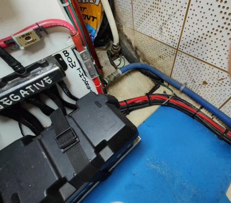
there should be a dc negative buss somewhere close by to attach the heaters negative wire.
is that clear enough?
 
btw, i don't know what you have for a meter. i'm assuming you know how to set it for ohms and volts respectively.
if not, ask for clarification please.
 
Thanks for the detailed steps

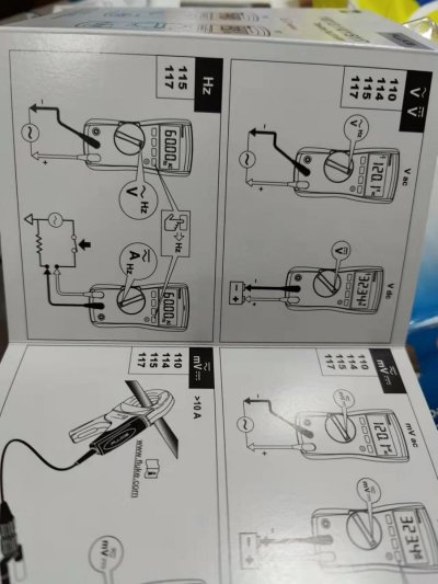
I was able to find the wire that is connected to the breaker, using the fluke 117 ohm reading (it showed 0.2 instead of 0 ohm).

Image_20240213000832.jpg
one problem in dc volt meter is, the reading is very sensitive, it fluctuates whenever my hand come close or moves away

i'm not sure how to read volts. the other prong should be connected to the negative polarity according to the manual. there are 3 items behind the service panel that look like dc hubs, does any of the thick black wires connect to the negative polarity?

Image_20240213000823.jpg

Image_20240213002202.jpg

first turn the breaker off. verify that there's no power to terminal 15 on the terminal strip. remove one of the wires marked 15 from the terminal strip. use the ohm meter and put one test probe on the output side of the breaker. this is the wire marked 15 on the breaker. put the other probe on one of the wires at the terminal strip. when you find the wire that has zero ohms you have found the right wire. that would be the wire that remains connected on the terminal strip. insulate the other wire with tape or something and tag it so you know what it is for future use.
now you will have a wire connected from the breaker to the terminal strip and an empty slot to place your new positive wire for the heater. while you have your meter handy, after you have identified the wire from the breaker and have it attached to the terminal strip, turn the breaker back on and verify that you have your 12 volt reading at terminal 15. (or whatever the voltage is at the positive buss, it should be whatever the batteries are at.)
there should be a dc negative buss somewhere close by to attach the heaters negative wire.
is that clear enough?
 
Last edited:
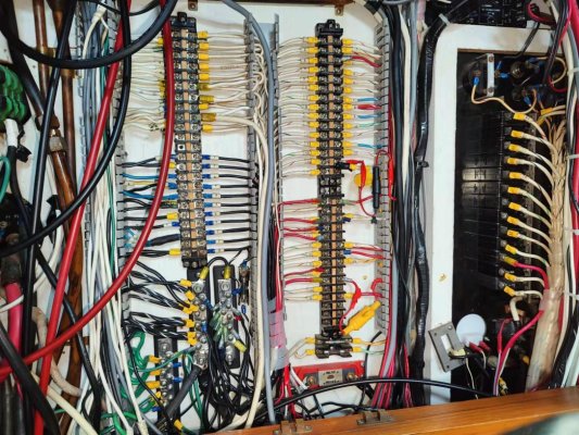
I looked back to your post #45 and see there’s another terminal strip loaded up with black wires. That’s probably the dc negative buss. It looks pretty busy there, but there’s likely a place to land the negative wire from the heater.
That buss should be supplied by a fairly large black wire.
If you pull the cover off the wire duct you might be able to find the black wire that goes with the #15 wire. If you pull that one, you’ll have a place to land the heater negative.
It’s common for the fluke mater to roll some random numbers in millivolts until you land on wires with good voltage on them. It’s just searching for a signal.

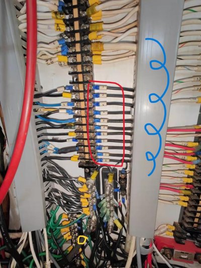
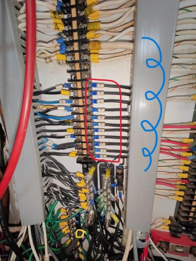
I labeled a duct cover using blue ink - i think this is the cover you said to pull off. the wires are first channeled through the cover before the cover is somehow fixed to the bulkhead. How to take the cover off?

I'm not sure which is terminal strip loaded with black wires. are the 8 black wires that I framed in red AC wires? the AC service panel also has 8 breakers so the numbers line up

Image_20240213105524.jpg

Image_20240211170443.jpg
 
The gray wire duct is a two piece assembly. The base, has all the fingers where the wires poke through. The cover snaps on. To remove it, simply squeeze the fingers and pull up in a sort of twisting motion. The cover is easily removed.
So, I’m not at the boat to verify, but if I had to guess, the dc negative buss would likely be the jumble of black wires on the two buss bars below the ones you circled. You need to carefully verify that this is the case. Follow the big black feed wires till you find where they connect, or follow some of the other wires to verify they are dc negative.
You can put your volt meter on the buss as well, to see if you have your 12 volts there, but follow some wires as well so you are absolutely sure of yourself. I see a ground buss there as well, but not sure if that’s an ac ground or ships bonding ground.
The electrician should have been more diligent about labeling things so you have distinct separation of ac and dc systems.

Thanks, I have removed the duct cover. but the black wires are not numbered , how to find the wire that is on the same circuit of the #15 positive wire?

I have tested the voltage b/t #15 breaker and the negative buss bar and got a reading -13.5V

Image_20240214110855.jpg

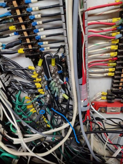
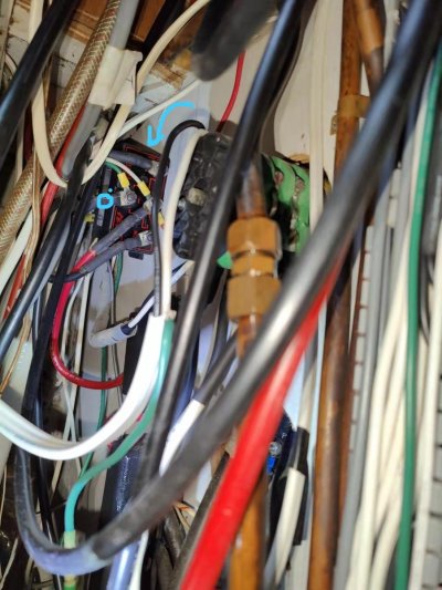
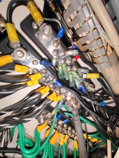
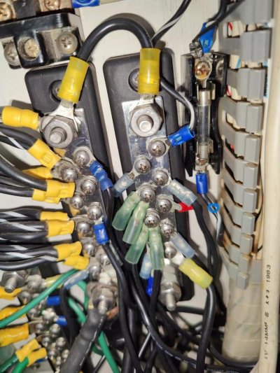
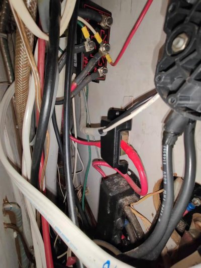
in the photo above, the thick black wire labeled in blue line goes through a hole at the bottom into the ER so that is likely connected to the battery negative. The black wire labeled in blue dot connects to another DC hub like device, as pointed to in the photo below -

Image_20240214110902.jpg
 
I have also confirmed the area in red frame is AC neutral wires. when I take #5 connector off, the microwave power is cut. there are multiple #4 wires each one is to an outlet
 

Attachments

  • Image_20240213105524.jpg
    Image_20240213105524.jpg
    162.2 KB · Views: 28
ok, quite a bit to unpack here. i was hoping that when you removed the cover you could follow the #15 wire from the terminal and see if it was bundled with one of the black wires from that buss. that would confirm the busses were dc negative.
also, just because you read 13 volts between wire 15 and what we assume is the dc buss doesn't mean we have positive identification. there are a couple of anomalies i'm concerned about. first, there's a small fuse attached to that buss. why a fuse on the negative side?
second, there's a buss of green wires in close proximity to those busses. what's that for?
the black wire that goes through the floor into the er, can you find it below and confirm it goes to one of the dc hubs in the er? that would really ease my concerns about those busses.
next, the wire you identify with the blue dot is attached to a relay of some sort. do you know what that is for?
now to post 69. those can not be ac neutral wires. (or at least shouldn't be) they are numbered and black which indicates ac hot coming from the breakers. be careful taking those off because you might get shocked if you're touching ground, or neutral, or anything connected to the boats dc negative.
at the least, it would be very unpleasant.
it's more likely that your ac neutrals are the group of white wires above the black numbered ones.
again, hard to see in your pictures because you don't show the wire duct with the cover off in that area. i'm wondering if there are jumpers from terminal to terminal. it's common to do that by using short wires going from a terminal, into the wire duct, and back out to an adjacent terminal, and so on, to make a connected buss.
the point is Jay, i want to be very careful with this. your electrical skills are limited. you're learning, but things can easily be misunderstood without thorough understanding of what's in front of you. your safety is most important.
so, positive identification on those alleged dc negative busses is what we need to establish. either by finding the black wire that goes with the #15 wire to the fridge area, or, following the large black wire into the er to verify connection to the dc hubs there.
 
Thanks for the warning. I did turn off the breaker, verify no voltage using a tester before working on the lines. I felt pretty comfortable doing it as if this should have been my career. The outgoing wires are mostly laid behind the panels, it is not easy to follow one wire to the fridge. I will verify the thick black wire later.

ok, quite a bit to unpack here. i was hoping that when you removed the cover you could follow the #15 wire from the terminal and see if it was bundled with one of the black wires from that buss. that would confirm the busses were dc negative.
also, just because you read 13 volts between wire 15 and what we assume is the dc buss doesn't mean we have positive identification. there are a couple of anomalies i'm concerned about. first, there's a small fuse attached to that buss. why a fuse on the negative side?
second, there's a buss of green wires in close proximity to those busses. what's that for?
the black wire that goes through the floor into the er, can you find it below and confirm it goes to one of the dc hubs in the er? that would really ease my concerns about those busses.
next, the wire you identify with the blue dot is attached to a relay of some sort. do you know what that is for?
now to post 69. those can not be ac neutral wires. (or at least shouldn't be) they are numbered and black which indicates ac hot coming from the breakers. be careful taking those off because you might get shocked if you're touching ground, or neutral, or anything connected to the boats dc negative.
at the least, it would be very unpleasant.
it's more likely that your ac neutrals are the group of white wires above the black numbered ones.
again, hard to see in your pictures because you don't show the wire duct with the cover off in that area. i'm wondering if there are jumpers from terminal to terminal. it's common to do that by using short wires going from a terminal, into the wire duct, and back out to an adjacent terminal, and so on, to make a connected buss.
the point is Jay, i want to be very careful with this. your electrical skills are limited. you're learning, but things can easily be misunderstood without thorough understanding of what's in front of you. your safety is most important.
so, positive identification on those alleged dc negative busses is what we need to establish. either by finding the black wire that goes with the #15 wire to the fridge area, or, following the large black wire into the er to verify connection to the dc hubs there.
 
@Bmarler
I followed these clues to snap some new photos -
#15 DC Ref belongs to factory original wiring where the the pos and neg wires from one cable would split and group into the separate pos and neg bundle at an earlier point. I was only able to trace pos and neg bundles in spiral looms into a hole, they then disappeared. it's difficult to tell which neg wire is the pair of the #15 wire

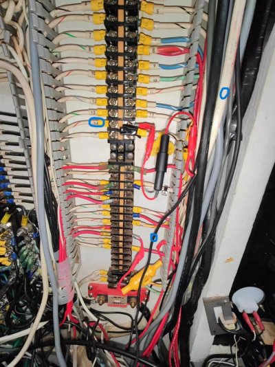
#14 GPS - Garmin 3210 chartplotter was new electronics added to the boat. the white cable splits inside the wire duct, so I was able to trace the negative leg to the buss bar (blue dotted). Does this also confirm that buss bar is DC negative?

Image_20240217232512.jpg

Image_20240217232456.jpg

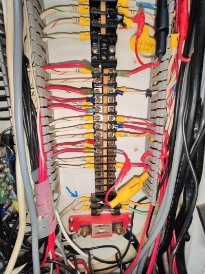
For the fuse attached to this buss bar, the fuse is connected up to the DC panel. From the front side, it looks like a fuse

Image_20240217232622.jpg
Image_20240217232627.jpg
Image_20240218000253.jpg


ok, quite a bit to unpack here. i was hoping that when you removed the cover you could follow the #15 wire from the terminal and see if it was bundled with one of the black wires from that buss. that would confirm the busses were dc negative.
also, just because you read 13 volts between wire 15 and what we assume is the dc buss doesn't mean we have positive identification. there are a couple of anomalies i'm concerned about. first, there's a small fuse attached to that buss. why a fuse on the negative side?
second, there's a buss of green wires in close proximity to those busses. what's that for?
the black wire that goes through the floor into the er, can you find it below and confirm it goes to one of the dc hubs in the er? that would really ease my concerns about those busses.
next, the wire you identify with the blue dot is attached to a relay of some sort. do you know what that is for?
now to post 69. those can not be ac neutral wires. (or at least shouldn't be) they are numbered and black which indicates ac hot coming from the breakers. be careful taking those off because you might get shocked if you're touching ground, or neutral, or anything connected to the boats dc negative.
at the least, it would be very unpleasant.
it's more likely that your ac neutrals are the group of white wires above the black numbered ones.
again, hard to see in your pictures because you don't show the wire duct with the cover off in that area. i'm wondering if there are jumpers from terminal to terminal. it's common to do that by using short wires going from a terminal, into the wire duct, and back out to an adjacent terminal, and so on, to make a connected buss.
the point is Jay, i want to be very careful with this. your electrical skills are limited. you're learning, but things can easily be misunderstood without thorough understanding of what's in front of you. your safety is most important.
so, positive identification on those alleged dc negative busses is what we need to establish. either by finding the black wire that goes with the #15 wire to the fridge area, or, following the large black wire into the er to verify connection to the dc hubs there.
 
Last edited:
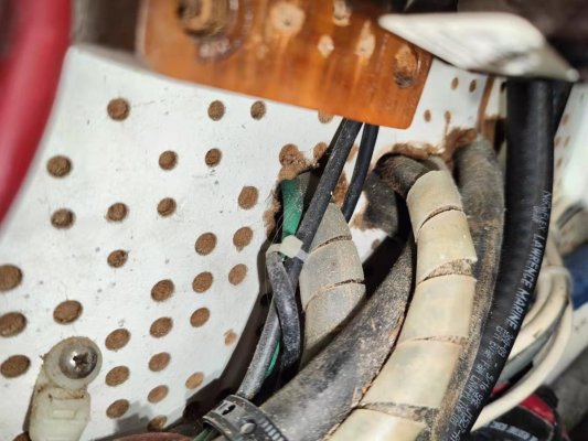
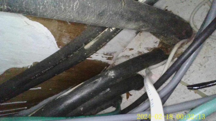
the DC black cables start from the portside dc hub neg, they go along the forward bulkhead over the bilge pump then enter a hole on the bulkhead. 5 black cables enter the hole

Image_20240217232518.jpg

Image_20240217232505.jpg

Image_20240217232552.jpg

behind the service panel, there are also 5 cables coming through the holes on the floor. almost certain these 5 cables are originated from the dc hub. is there some test that can confirm this?

IMG_0015.jpg

ok, quite a bit to unpack here. i was hoping that when you removed the cover you could follow the #15 wire from the terminal and see if it was bundled with one of the black wires from that buss. that would confirm the busses were dc negative.
also, just because you read 13 volts between wire 15 and what we assume is the dc buss doesn't mean we have positive identification. there are a couple of anomalies i'm concerned about. first, there's a small fuse attached to that buss. why a fuse on the negative side?
second, there's a buss of green wires in close proximity to those busses. what's that for?
the black wire that goes through the floor into the er, can you find it below and confirm it goes to one of the dc hubs in the er? that would really ease my concerns about those busses.
next, the wire you identify with the blue dot is attached to a relay of some sort. do you know what that is for?
now to post 69. those can not be ac neutral wires. (or at least shouldn't be) they are numbered and black which indicates ac hot coming from the breakers. be careful taking those off because you might get shocked if you're touching ground, or neutral, or anything connected to the boats dc negative.
at the least, it would be very unpleasant.
it's more likely that your ac neutrals are the group of white wires above the black numbered ones.
again, hard to see in your pictures because you don't show the wire duct with the cover off in that area. i'm wondering if there are jumpers from terminal to terminal. it's common to do that by using short wires going from a terminal, into the wire duct, and back out to an adjacent terminal, and so on, to make a connected buss.
the point is Jay, i want to be very careful with this. your electrical skills are limited. you're learning, but things can easily be misunderstood without thorough understanding of what's in front of you. your safety is most important.
so, positive identification on those alleged dc negative busses is what we need to establish. either by finding the black wire that goes with the #15 wire to the fridge area, or, following the large black wire into the er to verify connection to the dc hubs there.
 
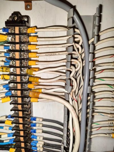
i also saw lots of jumpers in the AC neutral terminal strip

Image_20240217232604.jpg

there is also a jumper at the bottom of the DC terminal strip

Image_20240217232558.jpg

For the green wire buss bar, i saw at least one AC ground wire connected to it. could the same buss bar function as both AC ground and bonding ground?

For the secret dc relay, I cannot tell what it is except it's "made in Italy" and some info below

side facing portside
IMG_0006.jpg

side facing v-berth
IMG_0011.jpg

backside
IMG_0009.jpg

bottom
IMG_0013.jpg


Here is an overview of the wiring:

Image_20240218000848.jpg
 
Last edited:
Thanks for the new pictures, and the wide shot. The wide shot is very useful.
I think it’s safe to say the bundles of black wires on the pair of busses are in fact dc negative.
The green wires can be ac ground or bonding wires, but most likely ac ground. There should be a point where the ac ground, and the dc bond come together, but let’s not go down that path yet.
BTW, when you want to absolutely be certain of a wires identification you need to isolate it and use your ohm meter to verify it. If the ends are a long ways apart, use a long wire to extend your meter test leads temporarily.
In any case, I think you’re safe to use the circuit 15 and the black dc negative buss to power your heater as long as the breaker and wire size will carry the load.
 
I saw two ring connectors on the dc terminal strip were disconnected and tucked inside the wire duct, but there are no connectors removed from the dc neg buss bar. the reason may be the pos wires are labeled clearly but the neg wires are not, and it's difficult to determine which neg wire is the right one to remove when the PO upgraded electronics. I'd connect the neg wire to any of the screws on the dc neg buss bar

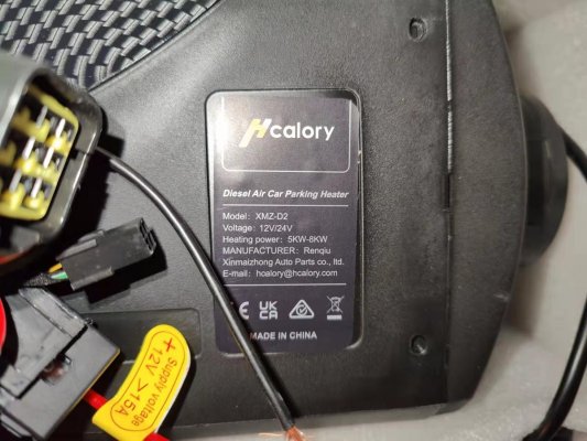
#15 breaker is rated 15A. but I just noticed the heater requires ">15A". will the #15 breaker still work?

Image_20240218104236.jpg

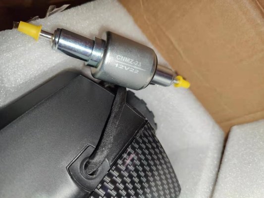
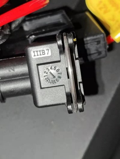
the pump model is CNMZ-23, 12V22 (meaning 22ml). there is a needle pointing to "9" on the pump cable, does it require 9A?

Image_20240218104231.jpg

Image_20240218104221.jpg


Thanks for the new pictures, and the wide shot. The wide shot is very useful.
I think it’s safe to say the bundles of black wires on the pair of busses are in fact dc negative.
The green wires can be ac ground or bonding wires, but most likely ac ground. There should be a point where the ac ground, and the dc bond come together, but let’s not go down that path yet.
BTW, when you want to absolutely be certain of a wires identification you need to isolate it and use your ohm meter to verify it. If the ends are a long ways apart, use a long wire to extend your meter test leads temporarily.
In any case, I think you’re safe to use the circuit 15 and the black dc negative buss to power your heater as long as the breaker and wire size will carry the load.
 
I saw two ring connectors on the dc terminal strip were disconnected and tucked inside the wire duct, but there are no connectors removed from the dc neg buss bar. the reason may be the pos wires are labeled clearly but the neg wires are not, and it's difficult to determine which neg wire is the right one to remove when the PO upgraded electronics. I'd connect the neg wire to any of the screws on the dc neg buss bar

#15 breaker is rated 15A. but I just noticed the heater requires ">15A". will the #15 breaker still work?

View attachment 145787

the pump model is CNMZ-23, 12V22 (meaning 22ml). there is a needle pointing to "9" on the pump cable, does it require 9A?

View attachment 145788

View attachment 145789
Due to the less than clear translation from Chinese evident on those labels, I
wouldn't automatically assume the heater will draw more than 15 amps. Once
you connect it you can verify its actual draw and keep or choose a new breaker.

The pump cable with the arrow probably refers to the month of manufacture.

For measuring amps, your Fluke 117 - a great meter, by the way - is limited to
10 amps and probably has an internal fuse protecting that circuit.
I would want to have a few of those fuses handy just in case when testing amps.
Fluke may offer an accessory to measure amps higher than the 117's 10 amp limit.
 
Last edited:
I have no idea whether that 15 amp breaker will be ok. I don’t know what the max amps of the heater are, or if the breaker will hold rated amperage or not.
I do know that the greatest draw happens at startup and shutdown( if the glow plug lights at shutdown). The rest of the time, it probably only draws about 3-4 amps. So, if the breaker holds through startup you’ll likely be ok.
You don’t have to add any amps for the fuel pump, it’s taken into consideration for the total heater amp draw.
 
It should be manufacturer date

Thanks for the highlighting the amp rating of 117. I would not have thought about it. I would use a 325 that can measure 40A.

Due to the less than clear translation from Chinese evident on those labels, I
wouldn't automatically assume the heater will draw more than 15 amps. Once
you connect it you can verify its actual draw and keep or choose a new breaker.

The pump cable with the arrow probably refers to the month of manufacture.

For measuring amps, your Fluke 117 - a great meter, by the way - is limited to
10 amps and probably has an internal fuse protecting that circuit.
I would want to have a few of those fuses handy just in case when testing amps.
Fluke may offer an accessory to measure amps higher than the 117's 10 amp limit.
 
14g wire is standard for a 15a breaker. But the supplied cable needs extension wires to reach the breaker. I don't have a way to measure exactly. The run would be longer than 20 ft. Is it necessary to use 10g wires for the extension?


I have no idea whether that 15 amp breaker will be ok. I don’t know what the max amps of the heater are, or if the breaker will hold rated amperage or not.
I do know that the greatest draw happens at startup and shutdown( if the glow plug lights at shutdown). The rest of the time, it probably only draws about 3-4 amps. So, if the breaker holds through startup you’ll likely be ok.
You don’t have to add any amps for the fuel pump, it’s taken into consideration for the total heater amp draw.
 
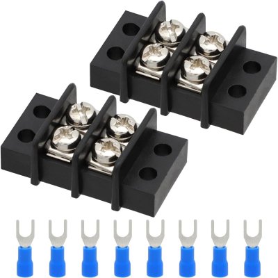
If I were doing this installation for myself, I would run new 10 gauge duplex boat cable from the breaker (terminal strip) to the heater location. Land them on a little barrier strip. Then shorten the heater wires and land them on the barrier strip. This way you don’t have a splice somewhere along the wiring run and have access to the connection for maintenance.
 
If I were doing this installation for myself, I would run new 10 gauge duplex boat cable from the breaker (terminal strip) to the heater location. Land them on a little barrier strip. Then shorten the heater wires and land them on the barrier strip. This way you don’t have a splice somewhere along the wiring run and have access to the connection for maintenance.

I think barrier strip here refers to a small terminal strip
61jSrYnh4CL._SL1500_.jpg

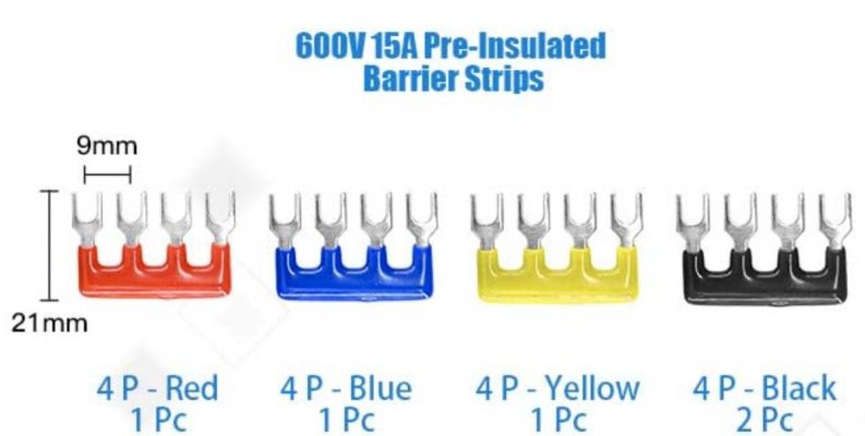
I saw the jumpers are also called barrier strips:

Screenshot 2024-02-19 123918.jpg

I'll get the first one.
 
Back
Top Bottom