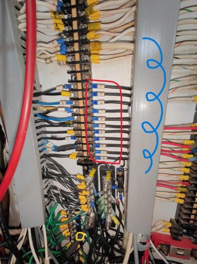
ok, quite a bit to unpack here. i was hoping that when you removed the cover you could follow the #15 wire from the terminal and see if it was bundled with one of the black wires from that buss. that would confirm the busses were dc negative.
also, just because you read 13 volts between wire 15 and what we assume is the dc buss doesn't mean we have positive identification. there are a couple of anomalies i'm concerned about. first, there's a small fuse attached to that buss. why a fuse on the negative side?
second, there's a buss of green wires in close proximity to those busses. what's that for?
the black wire that goes through the floor into the er, can you find it below and confirm it goes to one of the dc hubs in the er? that would really ease my concerns about those busses.
next, the wire you identify with the blue dot is attached to a relay of some sort. do you know what that is for?
now to post 69. those can not be ac neutral wires. (or at least shouldn't be) they are numbered and black which indicates ac hot coming from the breakers. be careful taking those off because you might get shocked if you're touching ground, or neutral, or anything connected to the boats dc negative.
at the least, it would be very unpleasant.
it's more likely that your ac neutrals are the group of white wires above the black numbered ones.
again, hard to see in your pictures because you don't show the wire duct with the cover off in that area. i'm wondering if there are jumpers from terminal to terminal. it's common to do that by using short wires going from a terminal, into the wire duct, and back out to an adjacent terminal, and so on, to make a connected buss.
the point is Jay, i want to be very careful with this. your electrical skills are limited. you're learning, but things can easily be misunderstood without thorough understanding of what's in front of you. your safety is most important.
so, positive identification on those alleged dc negative busses is what we need to establish. either by finding the black wire that goes with the #15 wire to the fridge area, or, following the large black wire into the er to verify connection to the dc hubs there.