2-shunts. Parallel or Series or does it matter?

The friendliest place on the web for anyone who enjoys boating.
If you have answers, please help by responding to the unanswered posts.

mvweebles

Guru
Joined
Mar 21, 2019
Messages
7,246
Location
United States
Vessel Name
Weebles
Vessel Make
1970 Willard 36 Trawler
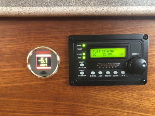
I have Victron SmartShunt for my solar controls; and a Magnum shunt for the inverter. Should they be cabled in series, parallel, or does it matter?

Simple diagram attached with three options (maybe there are other options?). Pretty sure #1 is the right direction, but would appreciate feedback from TF's Bigger Brain.

Thanks in advance -

Peter

Two Shunt Cabling Options.jpg
 
I would say series as putting them in parallel would split the load between them and give false readings.
 
They need to be in series as mentioned above.

Ted
 
Agree with post above. Series.
 
It depends on what you want to measure? If you want to measure the output of your solar panels the shunt you go into the output of your controller before it is tied into the batteries. The inverter shunt is in series with the main battery return. If you want both shunts in the main return then series them.
 
Are the shunts the same rating? If so, it's often possible to attach two metering devices to the same shunt. As long as each has a high enough input impedance, they will not impact each other. Easiest way to confirm is to try it.
 
Agree with TT, just use one shunt. Hook both to that shunt. Configure for the shunt sensitivity if necessary. In the modern world it is inconceivable that the input impedance of those devices would load a battery shunt (output impedance of the shunt is practically zero, input impedance of a modern inverter or solar controller practically infinite).
 
Agree with TT, just use one shunt. Hook both to that shunt. Configure for the shunt sensitivity if necessary. In the modern world it is inconceivable that the input impedance of those devices would load a battery shunt (output impedance of the shunt is practically zero, input impedance of a modern inverter or solar controller practically infinite).
The Victron smart shunt appears to be proprietary. It does not have separate small lugs go attach wires to a monitor as a typical shunt has. I guess I could drill and tap a 1/4"-20 screw, but not sure if that would skew something else?

Peter Screenshot_20230312_062020_DuckDuckGo.jpg
 
The Victron smart shunt appears to be proprietary. It does not have separate small lugs go attach wires to a monitor as a typical shunt has. I guess I could drill and tap a 1/4"-20 screw, but not sure if that would skew something else?

Peter View attachment 137078


That does complicate things a bit, but I think it's still workable. I'd just wire the other gauge or meter to the battery terminals on the shunt using ring terminals. Just be sure the battery and load cables are on the posts first so they are in direct contact with the shunt, then put the smaller ring terminals on top, then tighten the nut down.
 
You need only a #6 or #8 screw. They've used the two normal holes to connect their circuit board. Or do what TT suggests. Either would be better IMO than two shunts in series. What is the rating on the Magnum shunt? 500A/50mv is pretty standard.
 
I guess I could drill and tap a 1/4"-20 screw, but not sure if that would skew something else?

Peter View attachment 137078

1/4" is way too big (IMHO). Use #8 or #10. I don´t think it is a good idea to sense off the main cable connections on the shunt.
 
Even #6 is fine. There is no current going through the sensing connection. I don't think there is any problem sensing off the cable connections either, if done with the right ring terminals.
 
OP: Rather than drilling and tapping the Victron SmartShunt, I recommend buying a quality Blue Sea Systems 8255 DC Digital Current Shunt - 500A/50mVDC. Why? Most Victron equipment has a 5 year warranty which you would void by modifying the SmartShunt.

$58 on Amazon.

And the shunts should be in series for the reasons discussed up thread.
 
What’s the issue with shunts in series?
 
@Bmarler #15: No issue at all. For the described application it is the correct way to wire them.
 
Parallel 1&2 is the wrong way to connect shunts.
The Series figure would read the total current by each shunt for two independent instruments.
 
Last edited:
Note also that Blue seas says 66% of max. rating for continuous use.

I will guess that Victron has a similar rating but find out.

So what level of current are you anticipating? If over the continuous rating then be carefull. That goes for draws and recharging.

Ask both mfgrs. for some advice. A fan for cooling may help but find out.
 
Why does the inverter need a shunt? AMPs into and out of the battery will be tracked by the Victron. monitor.

Bruce
 
Note also that Blue seas says 66% of max. rating for continuous use.

I will guess that Victron has a similar rating but find out.

I saw that when I looked up the BSS shunt CharlieJ referenced. I'm a 30A boat (360A @ 12VDC) so should not have a problem staying below that limit. I de-rated my water heater element to 750W and there's not much else to draw much. Air Conditioning will run on generator when needed

Peter
 
I have two shunts wired in series about 6 inches apart. One is a Magnum and the other is a Balmar... They never agree there is always ambiguity and I'm sure if I measured the current with my DVOM, I would get a third value.
 

Attachments

  • Balmar current.jpg
    Balmar current.jpg
    100 KB · Views: 25
The amperage is marked on Victron shunts. Look at the brass posts.

500 is the stock but higher amp rates are available.

Bruce
 
I saw that when I looked up the BSS shunt CharlieJ referenced. I'm a 30A boat (360A @ 12VDC) so should not have a problem staying below that limit. I de-rated my water heater element to 750W and there's not much else to draw much. Air Conditioning will run on generator when needed

Peter

I am glad to see you are aware of that. I have talked to people who had no idea of the difference and it is important.
 
I have two shunts wired in series about 6 inches apart. One is a Magnum and the other is a Balmar... They never agree there is always ambiguity and I'm sure if I measured the current with my DVOM, I would get a third value.

5 amps is a pretty big discrepancy. Is there a procedure for zero-ing them? I know my Cruz pro meter has a procedure that runs overnight to find the best zero on the amp draw.
I’d like to believe the balmar is accurate, but I don’t know if you’re pulling power there or not.
 

Latest posts

Back
Top Bottom