Windlass wiring

The friendliest place on the web for anyone who enjoys boating.
If you have answers, please help by responding to the unanswered posts.

Lou_tribal

Guru
Joined
Jan 20, 2016
Messages
4,375
Location
Canada
Vessel Name
Bleuvet
Vessel Make
Custom Built
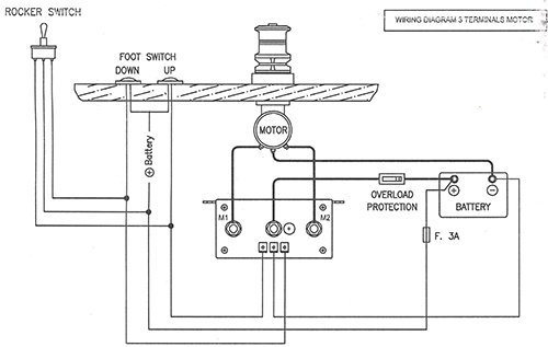
In a separate discussion I posted a picture of my old windlass/capstan.
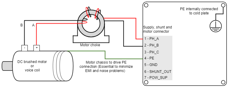
I am wondering why the electric motor shows 3 wires, one negative and 2 connected together (red and green) to the positive as shown below.
317825785.jpg

Would anybody have an idea?

L
 
This or that....
 

Attachments

  • 3_TERMINAL_WIRING_DIAGRAM.jpeg
    3_TERMINAL_WIRING_DIAGRAM.jpeg
    68.6 KB · Views: 26
  • TritonDCmotorWiring.png
    TritonDCmotorWiring.png
    37.1 KB · Views: 24
At first I was thinking about the up/down shown on the upper diagram but there is only a pull/push switch to activate/deactivate it and as the two directions wires are connected together this would not work.

The second diagram makes more sense but that means it was not wired properly as the PE and Positive are connected together.

Thank you!

L
 
If the motor is dual voltage , 12/24, the connections would need to be changed so three wires to suit
the supply volts.

Otherwise I too would expect up/down by polarity reversal.

Try a motor shop. I,ll suggest they can tell you conclusively.
 
Last edited:
From Psneel second diagram and some other search I did I would tend to a frame ground wire (the green one on the picture). I will test continuity between moto frame and the wire.

L
 
Back
Top Bottom