Balmar ARS-5 vs MC 618 Regulators

The friendliest place on the web for anyone who enjoys boating.
If you have answers, please help by responding to the unanswered posts.

Diverrob

Senior Member
Joined
Jan 5, 2018
Messages
122
Location
Canada
Vessel Name
Sounder
Vessel Make
Mainship 34T
Good day everyone and Merry Christmas!

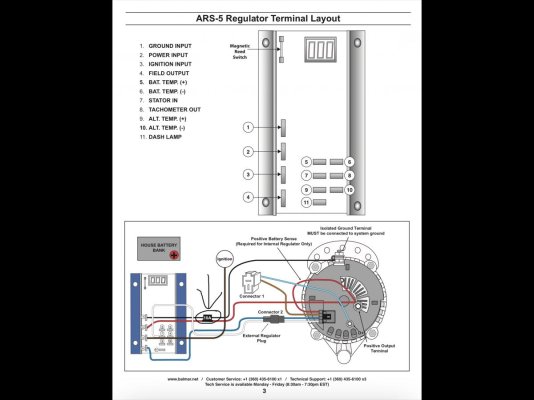
I currently have a Balmar ARS-5 external regulator working my Balmar 150A alternator. I have gone through the advanced programming and I believe I have it where it should be. After a couple years of running it the only thing I can’t seem to do is have the voltage sensing come from the battery post, it needs to be coming from the back of the Alternator. When connected to the battery post the fuse pops every time I use the thrusters (which I thought were isolated but seem to get pass the isolator when on the post). I also have the SG 200 smart meter which I like and use with the Bluetooth app.

My question is upgrading to the new MC 618 worth the trouble (and cost)? This is what I see as pro vs con…

Pro

Independent voltage sensing for better charge performance
Integration with the SG 200 App for remote monitoring
Simple programming with the Bluetooth App
A little future proofing with the ability to handle Firefly and Li batteries

Con

Price as I already have a perfectly working ARS-5
Potential little gain in efficiency of charging
“Future proofing” too early as my batteries will be with me for 3-4 more years

I’m interested to hear from the hive mind on this issue, cheers and thanks

Rob
 
Can't help you with the difference between the two.

But, if you install a sensing wire, be sure that it can’t be isolated from the alternator cable. If the sensing wire can't see the alternator output, the regulator will raise the voltage from the alternator to get it with in the charging parameters. Lots of stuff doesn't tolerate excessive voltage.

Ted
 
I switched out my ARS-5 for dual Wakespeed WS500's. If you go the "switching route" may want to take a look at that option as well...
 
Give Balmar a call very nice and helpful crew. They have helped me several times.
Don
 
all of the balmar regulators seem so similar to me. from a performance standpoint i don't think there's much to be gained.
if your batteries are going to last another few seasons i'd wait and do any upgrades at that time based on what type of batteries you install, and if you really want/need remote monitoring or programming.
i feel like remote programming would only be used once or twice, when commissioning or tweaking the installation. would be handy but not required. remote monitoring? not important to me when i have a good voltage and amperage gauge set on the dash already.
the performance gain for dollar outlay doesn't pencil out for me.
 

Attachments

  • 0FDADCD2-55C4-4185-B9B5-6C286A54A7C3.jpg
    0FDADCD2-55C4-4185-B9B5-6C286A54A7C3.jpg
    91 KB · Views: 44
all of the balmar regulators seem so similar to me. from a performance standpoint i don't think there's much to be gained.
if your batteries are going to last another few seasons i'd wait and do any upgrades at that time based on what type of batteries you install, and if you really want/need remote monitoring or programming.
i feel like remote programming would only be used once or twice, when commissioning or tweaking the installation. would be handy but not required. remote monitoring? not important to me when i have a good voltage and amperage gauge set on the dash already.
the performance gain for dollar outlay doesn't pencil out for me.

I’m kinda leaning that way also but wanted to look at all angles. Thanks for your input
 
The inline 10A fuse on the regulator power supply (see pic below)

Seems to me very odd that the fuse would blow due to moving the sense line. It suggests either something is wired funny, or the field is actually drawing more than 10 A. I would not expect a Balmar 150A alternator to draw that much, more like 5A. I think I would try to solve that problem before looking at a new regulator, which might have the same problem.

Moving the sense line would make the regulator drive the field a little harder to account for the voltage drop to the battery, but once the field is saturated it should accept no more. That would happen even with the sense line at the alternator if the batteries are low (unless there is very small cable to the batteries).

Do you have a clamp ammeter to measure the current?

Yes I was thinking exactly the same thing however when I put the clamp meter on the line and hit the thrusters I briefly saw 18A before the fuse popped. Without touching the thrusters it nominally shows 4ish amps. I will draw a little schematic of how the system is wired showing the battery isolator to better describe what is going on. Once I put the sensing wire back to the alternator everything is great.
 
It seems like somehow you must be drawing spurious current through that fused line. It really should only supply the regulator electronics (well <1 A) and the field current, around 4 or 5 max.

Thrusters may lower the battery side voltage way low, like 8V. If there is a current path through that fuse that might also supply the battery and/or thruster, it might be sharing some current.
 
Ok so please excuse the quality of the drawing but I hope this can help describe my system.

- The isolator is a new Victron 250A two battery isolator
- Alternator is a Balmar 150A
- regulator is a Balmar ARS-5

If I move the power and ground wires from the alternator to the battery posts then the fuse pops when I use the thrusters. In the configuration below everything works but there is a small difference in voltage sensing due to line loss.
 

Attachments

  • 526FF0A2-A265-4289-A78E-76B02B5D521D.jpg
    526FF0A2-A265-4289-A78E-76B02B5D521D.jpg
    67 KB · Views: 16
Hard for me to imagine the specific problem, but: The ARS doesn't have external sense so you have to move the power supply wires for the regulator to achieve remote sense. If the voltage on the thruster sags, ground at the alternator may also rise by a volt or two, putting it above the ground that the regulator is seeing at the house battery. That may cause it some grief since when the field is shut off (it is a PWM signal) it could be trying to sink current from the raised ground back to the house ground or some other nonsense it didn't expect.

To get to the bottom of it might require a recording oscilloscope or something that can record the transient voltages and currents. If the problem is differing power and grounds (seems like it must be as that is all you are changing) then perhaps the 614/618 *might* solve it as it can remain powered at the alternator, and only sense house voltage with the bespoke sense line that the 614 provides. A simple test would be to put a voltmeter between the ground post on the alternator and the ground post on the house battery and operate the thruster. If you get much of a reading (like > 0.5V) then I'd be a little worried. Doesn't matter how the regulator is hooked up when you do that test. Differences in the +12 side would be less of a concern as the regulator should be designed to expect that. Another slightly riskier test would be to move only the +12 for the regulator to the house, leaving the ground side at the alternator. If there is something really bizarre going on this could risk "bricking" the regulator so I'd be careful with that one. It really should work in that configuration but there are reasons it could be fragile. It might tell you that grounds are at fault, but I would only do that as a test, not a solution.
 
Last edited:
Hard for me to imagine the specific problem, but: The ARS doesn't have external sense so you have to move the power supply wires for the regulator to achieve remote sense. If the voltage on the thruster sags, ground at the alternator may also rise by a volt or two, putting it above the ground that the regulator is seeing at the house battery. That may cause it some grief since when the field is shut off (it is a PWM signal) it could be trying to sink current from the raised ground back to the house ground or some other nonsense it didn't expect.

To get to the bottom of it might require a recording oscilloscope or something that can record the transient voltages and currents. If the problem is differing power and grounds (seems like it must be as that is all you are changing) then perhaps the 614/618 *might* solve it as it can remain powered at the alternator, and only sense house voltage with the bespoke sense line that the 614 provides. A simple test would be to put a voltmeter between the ground post on the alternator and the ground post on the house battery and operate the thruster. If you get much of a reading (like > 0.5V) then I'd be a little worried. Doesn't matter how the regulator is hooked up when you do that test. Differences in the +12 side would be less of a concern as the regulator should be designed to expect that. Another slightly riskier test would be to move only the +12 for the regulator to the house, leaving the ground side at the alternator. If there is something really bizarre going on this could risk "bricking" the regulator so I'd be careful with that one. It really should work in that configuration but there are reasons it could be fragile. It might tell you that grounds are at fault, but I would only do that as a test, not a solution.

Ok i will give your first test a try but won’t bother with the second one ?. I’m not exactly sure what to do if this turns out to be a ground issue. From what I can see both the thruster and house share the same ground and I don’t know how I would go about isolating them. Honestly I could simply adjust the regulator to compensate for the loss in voltage and leave the power and ground at the alternator. At this point I’m just geeking out a little. When cruising the batteries will get very close to 100% within a few hours (3-5) based on my usage in the past. Thanks for your input on this, I appreciate learning from the group.

Rob
 
If the isolator is the newer argofet the voltage drop shouldn’t be more than .02 volts. (Or thereabouts) there will be slightly more when you include the cables and connectors. You can measure to see what the difference is and program the ars to compensate right?
If you see differences in the negative sides bigger cables might be helpful?

I should read more carefully. You already mentioned programming to compensate. Carry on….
 
I switched out my ARS-5 for dual Wakespeed WS500's. If you go the "switching route" may want to take a look at that option as well...

A 2nd vote for the Wakespeed WS500 for the following reasons:

  • Ease of install- simply wire according to the harness instructions.
  • Ease of programming- Rick at Wakespeed has charging parameters for most CF and LFP battery manufacturers and Victron specs ready to download.
  • Ease of connectivity- A simple CAT-5 cable connects the regulators, assigns master and slave, and controls the output of the alternators.
 
Ok so went down to the boat flashed it up and put a meter from the negative at the alternator and the negative on the house bank. Then I functioned both thrusters and watched the meter… nothing more than 0.03v so I don’t think this was the issue that DDW suggested above. Anyway I. Just going to leave it alone and possibly tweak the regulator to compensate for the minimal voltage drop. Thanks for your input!

Rob
 
If the isolator is the newer argofet the voltage drop shouldn’t be more than .02 volts. (Or thereabouts) there will be slightly more when you include the cables and connectors. You can measure to see what the difference is and program the ars to compensate right?
If you see differences in the negative sides bigger cables might be helpful?

I should read more carefully. You already mentioned programming to compensate. Carry on….

Even with a Schottky diode isolator you will have around 0.3 - 0.5V, not 0.02V drop. You can bandaid it with setting the voltages higher, but go for the minimum drop (0.3V end of things) as you will only get a larger drop at high currents when regulation is less of a concern.

Ok so went down to the boat flashed it up and put a meter from the negative at the alternator and the negative on the house bank. Then I functioned both thrusters and watched the meter… nothing more than 0.03v so I don’t think this was the issue that DDW suggested above. Anyway I. Just going to leave it alone and possibly tweak the regulator to compensate for the minimal voltage drop. Thanks for your input!

Rob
0.03V is certainly not an issue. Must be something else. If the grounds are well tied (and it sound like they are) then moving just the positive to the battery is not much risk.
 
Even with a Schottky diode isolator you will have around 0.3 - 0.5V, not 0.02V drop. You can bandaid it with setting the voltages higher, but go for the minimum drop (0.3V end of things) as you will only get a larger drop at high currents when regulation is less of a concern.


0.03V is certainly not an issue. Must be something else. If the grounds are well tied (and it sound like they are) then moving just the positive to the battery is not much risk.

Victron claims .02v drop at low currents with their new isolators, .1 v drop at high currents. These are what they call argofet isolators, not diode isolators. I don’t particularly like isolators as a rule, but if I had to install one I’d look at those.
Since he mentioned a new isolator, I thought maybe he had this.

Yes sorry for not making that clear my isolator is a new Victorian so basically no voltage drop across it.
 
That isolator has to be the reason the fuse pops. It’s the only thing in the path. Something about the new circuit is not agreeing with the ars regulator. Balmar might be able to shed some light on the reasoning, or whether or not a new regulator will fix it. Personally, for the couple tenths of a volt I’d just program around it.
 
OK a FET isolator will have low forward voltage. I didn't realize Victron made them.

When you operate the thruster, the +12 bus on the thruster and alternator side of the isolator will likely drop below house voltage, shutting off the current flow from the house battery. You still have the connection from house to field to ground through the ARS though. I'd think the field resistance would be too much to allow more than about 5 amps current to flow - but something is going on.

As another experiment, you could temporarily connect the two banks together bypassing the isolator (for example just connect both battery leads to BAT1 output on the isolator), then run with the ARS connected to the house. I'd expect that to work, and would prove the isolator was part of the problem.

I originally didn’t want to have the isolator but in order to have the alternator charge both the hoist and thruster banks I found I needed one. If I connect both banks together then operate the thrusters they pull sooooo much power that the fuses on my house bank pop. It pulls power through the charging line on the alternator and there are only 200A fuse there.
 
A charge relay may have been a better choice than the isolator. They do the same thing essentially, but in a slightly different manner. There’s no break in the wire going to the primary bank, presumably where the sensor would live.
 
A charge relay may have been a better choice than the isolator. They do the same thing essentially, but in a slightly different manner. There’s no break in the wire going to the primary bank, presumably where the sensor would live.

Well I thought about that however I didn’t think they would disconnect quick enough when the thrusters were working to prevent pulling power from the house bank through the alternator charging cables. Unless I’m missing something (or more likely not understand correctly) there would still be a a period of time when the relay is closed allowing power to be sourced from any available batteries. This will cause the fuse on the alternators to blow as the thrusters draw a HUGE amount of power immediately.
 
Well I thought about that however I didn’t think they would disconnect quick enough when the thrusters were working to prevent pulling power from the house bank through the alternator charging cables. Unless I’m missing something (or more likely not understand correctly) there would still be a a period of time when the relay is closed allowing power to be sourced from any available batteries. This will cause the fuse on the alternators to blow as the thrusters draw a HUGE amount of power immediately.

There would most certainly be a lag time for disconnecting. I don’t see how it would blow the alternator fuse though. The alternator should be fused for its output. The alternator won’t put out more than rated current just because the thrusters are on. (Unless I’m missing something)
 
It would be interesting to see the complete schematic of the DC system on this boat. There seem to be several things going on that shouldn't be.
 
There would most certainly be a lag time for disconnecting. I don’t see how it would blow the alternator fuse though. The alternator should be fused for its output. The alternator won’t put out more than rated current just because the thrusters are on. (Unless I’m missing something)

The reason the fuse blows when the thrusters are activated, the current draw is seen by the charging wire from the alternator (with no isolator in place). Because there is a delay in opening the switch the draw from the thrusters through the charging (positive) wires suppling both the house and thruster banks will exceed the fusing put in place to protect them when charging (max 150A output with 200A fuses). this will happen with or without the engine up and running. I have a full schematic of the system somewhere I just need to find it and will post to help explain. I really appreciate all the help on this and apologize for the difficulties I have in my explanation, I’m still learning everyday it seems ?

Rob
 
The reason the fuse blows when the thrusters are activated, the current draw is seen by the charging wire from the alternator (with no isolator in place). Because there is a delay in opening the switch the draw from the thrusters through the charging (positive) wires suppling both the house and thruster banks will exceed the fusing put in place to protect them when charging (max 150A output with 200A fuses). this will happen with or without the engine up and running. I have a full schematic of the system somewhere I just need to find it and will post to help explain. I really appreciate all the help on this and apologize for the difficulties I have in my explanation, I’m still learning everyday it seems [emoji2]


Rob
I think Bmarler was talking about the 10a fuse. That's the puzzling and unexplained challenge.

I'd suggest that blowing the 200a so easily points to an inadequately sized or tired thruster bank. It might be time to do a load test.

I'll throw this out to the experts here and am happy to be challenged. It seems to me that charging two banks with a single regulator is problematic at the best of times. If you're in the mood to make changes I'd suggest getting rid of the isolator and the connection between the two banks. Direct the alternator output to the house bank only, and power the regulator from there for optimal voltage sensing. Then charge the thruster bank with a dc-dc charger powered from the house bank.

My rationale for doing this on my boat was that it ensures optimal charge for both banks, allows you to mix battery types between banks with dedicated charge profile, and limits draw on the house system to the capacity of the charger. The Victron 30a charger I used is configured to turn on when the house bank is being charged.

This is essentially the configuration that Balmar recommends using their Duo Charge when there are two banks. Maybe you have that now for your start battery.

Well that sure would fix the problem and well worth looking into, thanks for the info much appreciated.
 
Back
Top Bottom