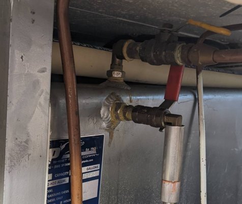
leaking shut-off valves for sight gauge

The friendliest place on the web for anyone who enjoys boating.
If you have answers, please help by responding to the unanswered posts.

Pat T

Senior Member
Joined
Sep 6, 2019
Messages
216
Location
United States
Vessel Name
Moondance
Vessel Make
Grand Banks CL 42
These push button fuel shut-off valves don't always seat and then leak. It looks like they can be disassembled and rebuilt with maybe an O ring or two but I have no info on this valve. Have you fixed yours or did you replace with a ball valve? Any info appreciated.
Sorry for the sideways pic.
 

Attachments

  • IMG_3209[1].jpg
    IMG_3209[1].jpg
    83.1 KB · Views: 24
  • IMG_3210[1].jpg
    IMG_3210[1].jpg
    98.9 KB · Views: 18
LDI Industries makes sight gages. It's all they do. I went with these with borosilicate tube protected in an aluminum cage. Needle valves control fluid flow. I realize they are not push-bottom momentary valves, but my thinking was they LDI seems to make high quality gages for industrial applications.

https://www.grainger.com/product/LDI-INDUSTRIES-Closed-Circuit-Liquid-Level-1U946

If I had it to do all over again, I would have my fiberglass tanks fabricated with an indent for sight gages - I believe Nordhavn is one of the builders who does this. Very sano install.

Peter
 
Last edited:
That's an interesting push button valve. I haven't seen one like that before. I wonder what the significance is of the arrow? For a sight gauge I think fluid would need to flow in both directions, right?


I think I posted a link to these Apollo self-closing valves that are commonly used on boats the need to meet CE certification for Europe.


https://www.amazon.com/Apollo-Valves-76-503-01A-Standard-Stainless/dp/B071JD61G9


The link is for a stainless version, but there are brass versions too. Not cheap, but they work well, and close as soon as you release the lever.

Does CE also require top-feed tubes on tanks? If so, if a boat had an old leaking saddle tank, replacement of one tank woth two tanks would require top-feed tubes and a manifold to manage four tanks (two each side) instead of two, correct?

Peter
 
Last edited:
That's an interesting push button valve. I haven't seen one like that before. I wonder what the significance is of the arrow? For a sight gauge I think fluid would need to flow in both directions, right?


Yeah, can't figure out the arrow. Flow is definitely 2 way.
 
Why so complicated.
Brass 1/2 inch ball valve is $20 or less at any big hardware or plumbing shop.
 
That's an interesting push button valve. I haven't seen one like that before. I wonder what the significance is of the arrow? For a sight gauge I think fluid would need to flow in both directions, right?


Yeah, can't figure out the arrow. Flow is definitely 2 way.

The arrow usually indicates a free flow direction, or intended flow direction. Being a spring loaded valve like that leads me to believe it’s essentially a check valve with a push button bypass for free flow both directions.
 
Does CE also require top-feed tubes on tanks? If so, if a boat had an old leaking saddle tank, replacement of one tank woth two tanks would require top-feed tubes and a manifold to manage four tanks (two each side) instead of two, correct?

Peter


I'm not sure about CE in that regard, but my guess is that they do not have such a requirement. I say that because the standard fuel setup on Nordhavns are large gravity feed fuel lines from the main tanks to a supply/day tank where it is then drawn/returned by consumers. Those gravity feed lines are all from ports at the bottom of the tanks, and I have never seen or heard of a boat where they have been removed, including a number of CE boats.
 
The arrow usually indicates a free flow direction, or intended flow direction. Being a spring loaded valve like that leads me to believe it’s essentially a check valve with a push button bypass for free flow both directions.


Interesting. So if installed "correctly", the sight tube level would drop with the tank level, and you would only need to push the button to refill the tube when you fill the tank? That would be pretty slick, but I would wonder about the opening pressure of the check valve, and resulting difference in indicated vs tank fuel levels. Might be just fine, or close enough, but I'd want to know.
 
That's an interesting push button valve. I haven't seen one like that before. I wonder what the significance is of the arrow? For a sight gauge I think fluid would need to flow in both directions, right?


Yeah, can't figure out the arrow. Flow is definitely 2 way.

Valves sometimes have a flow direction indicated. When installed with the pressure source upstream (according to the arrow) the valve stem seal is not subject to pressure (and possible leakage) when the valve is closed.

If these valves are in fact "check valves" - which I doubt - they would give erroneous level readings due to the cracking pressure of the check valve.
 
Interesting. So if installed "correctly", the sight tube level would drop with the tank level, and you would only need to push the button to refill the tube when you fill the tank? That would be pretty slick, but I would wonder about the opening pressure of the check valve, and resulting difference in indicated vs tank fuel levels. Might be just fine, or close enough, but I'd want to know.

the level probably won't drop automatically due to spring pressure holding the valve shut. impossible to know what the spring pressure is without having the spec of the valve.
the only time an accurate reading can be taken is when the valve is actuated.
of course, this is all speculation from looking at the valve picture and prior experience with similar plumbing pieces.
i get why they installed those in the first place, as they are automatically closing valves. personally, i'd prefer a ball valve. as was mentioned, those can be serviced, but the tank needs to be empty to do it.
 
. . . It looks like they can be disassembled and rebuilt with maybe an O ring or two but I have no info on this valve. . . QUOTE

You could remove the upper valve with fuel still in the tank and take it apart and see how it works/seals.

Do send us pictures of the disassembled valve!
 
Found out from Grand Banks it was a Guidi (Italian) valve. From the attached Pdf it looks to be an O ring and a thicker type of seal that would be the culprit. I've emailed them for info on rebuilding. We shall see but I am leaning toward replacing them with ball valves as suggested.
The next project, maybe another thread, is how to drain fuel from one tank into the other tank so that I can replace the lower sitting valve and not dump diesel out all over the place.
 

Attachments

  • push button valve.pdf
    62.7 KB · Views: 28
Found out from Grand Banks it was a Guidi (Italian) valve. From the attached Pdf it looks to be an O ring and a thicker type of seal that would be the culprit. I've emailed them for info on rebuilding. We shall see but I am leaning toward replacing them with ball valves as suggested.
The next project, maybe another thread, is how to drain fuel from one tank into the other tank so that I can replace the lower sitting valve and not dump diesel out all over the place.
I would attempt to rebuild them. These valves are the standard type used on oil
storage tanks which, like boat fuel tanks, can be unattended for long periods.
Unlike ball valves, they are impossible to forget to close. The o-rings look common.
 
Last edited:
The next project, maybe another thread, is how to drain fuel from one tank into the other tank so that I can replace the lower sitting valve and not dump diesel out all over the place.


Run the tanks down to a point that you can then pump fuel from one tank to another.
It is not a big deal. Just needs a small fuel resistant pump to move a few gallons a minute.

I did this many years ago as both tanks had leaks at the fuel feed valves at the tank bottoms.

Once you are sure the tanks, both, are below the 1/2 way level pump away.
THere will be some fuel spilled so be prepared.

Thanks, was thinking of doing this. Maybe I should build some sort of system with a pump and a filter attached ? I'm somewhat worried I will be sturring up crud from the bottom the the tanks. Anyway, I have run the tanks down to about 1/3 (100 gallons) and would like to get at least to 1/4 before I would attempt this project.
 
The next project, maybe another thread, is how to drain fuel from one tank into the other tank so that I can replace the lower sitting valve and not dump diesel out all over the place.


Run the tanks down to a point that you can then pump fuel from one tank to another.
It is not a big deal. Just needs a small fuel resistant pump to move a few gallons a minute.

I did this many years ago as both tanks had leaks at the fuel feed valves at the tank bottoms.

Once you are sure the tanks, both, are below the 1/2 way level pump away.
There will be some fuel spilled so be prepared.

I have two 75-gallon tanks and after being sure they were both less than 50% full, I connected my Xchang-R oil change system up the them and quickly transferred diesel for one the the other.
 
Found out from Grand Banks it was a Guidi (Italian) valve. From the attached Pdf it looks to be an O ring and a thicker type of seal that would be the culprit. I've emailed them for info on rebuilding. We shall see but I am leaning toward replacing them with ball valves as suggested.
The next project, maybe another thread, is how to drain fuel from one tank into the other tank so that I can replace the lower sitting valve and not dump diesel out all over the place.

I replaced both of the valves for the site tubes on our grand banks with the tanks 1/2 full. Plug the fuel tank vent with paper towel, have someone hold a shop vac hose in the fuel fill, and replace the valves. First side caused a major pucker factor. Lol. The other side was easy. It really works!!
 
. . . It looks like they can be disassembled and rebuilt with maybe an O ring or two but I have no info on this valve. . . QUOTE

You could remove the upper valve with fuel still in the tank and take it apart and see how it works/seals.

Do send us pictures of the disassembled valve!

I ended up hiring out to do this job. It was just one of those jobs I didn't want to do. He had a nice battery operated pump and all the required fittings to pump from tank to tank. It would have taken me 4 times longer to do the job.
As requested here is a shot of the break-down of the valve. One normal sized O ring and one beveled type ring could have been replaced to rebuild these things. After 22 years the rubber was pretty hard. In hindsight (always 20/20 !) I could have just unscrewed the button and pulled out the stem that holds the smaller O ring and replaced that O ring. You can see that O ring in the pic on the right. No fuel would spill out while you have this stem all the way out . I believe replacing top O ring would been sufficient to stop my intermittent leaks.
But now I have 4 new valves and I should be good for 20 more years. And if they need rebuilding I have the knowledge to know what has to be done......if I can remember.
 

Attachments

  • IMG_3371[1].jpg
    IMG_3371[1].jpg
    177.9 KB · Views: 13
  • IMG_3375[1].jpg
    IMG_3375[1].jpg
    70.6 KB · Views: 13
Back
Top Bottom