replace a gfci outlet

The friendliest place on the web for anyone who enjoys boating.
If you have answers, please help by responding to the unanswered posts.
I was not able to find similar stuff nearby

Do you know an alternative to that stress relief fitting that is also sold in the states?

Not only is that fitting outrageously expensive, its designed to be assembled into a pipe fitting using 1/2" NPT threads, note there is no locking nut on the mount side. Really unusual thereby justifying the expense.
It won't thread into you selected box correctly.

Find another one the right thread size for your box with the locking nut. To make the rubber gripping insert fit your 3 individual wires you may have to make them as round as you can using a couple layers of heat shrink.
 
The 3m link that I forwarded contains a dizzying array of connectors, insulated using nylon or vinyl, heat shrinked, or uninsulated along with wire and screw size requirements, plus you get to sometimes chose if you want a cheaper butt seam for the barrel or the more expensive brazed seam.
It's all described in the text for each connector. I have no idea if the insulated and heat shrinked connectors are the most prolific of 3M's offering.

Other than getting the wire and screw size right and getting some heat shrink on, most of the above should not really matter with what you are doing, as you, nor I, are Boeing.

Furthermore, other than for a temporary connection that will be replaced, I don't use any kind of insulated connectors, only non-insulated ones that I crimp, solder, (lets not start that argument please) clean, heat shrink and then mount, correctly. The solder excludes moisture and ensures a gas tight, connector to wire connection.
The only reason I bring this up is that as I don't use them, I can't direct you to a favoured supplier.

Finally I selected the 3M link only as it displayed the locking fork design quite well. It may be such that some or all of those 3M connectors are unavailable to us mere mortals or if they are, you many have to buy a package of 100 pieces or more. Again we're not Boeing.

Ancor, that well known marine brand does not seem to have a locking fork option, so that means you will have to find a supplier that has them in the quality, type, size and quantity that fits the bill.
 
Agree with the outlined steps, will be looking if I can find similar connectors. The connectors are for the new grounding wire. The existing wires are already very short, the location of the outlet is also restricted by peripheral systems, so to change the existing connectors may be too difficult.

What heat shrink should be used around the rubber inserts?


The 3m link that I forwarded contains a dizzying array of connectors, insulated using nylon or vinyl, heat shrinked, or uninsulated along with wire and screw size requirements, plus you get to sometimes chose if you want a cheaper butt seam for the barrel or the more expensive brazed seam.
It's all described in the text for each connector. I have no idea if the insulated and heat shrinked connectors are the most prolific of 3M's offering.

Other than getting the wire and screw size right and getting some heat shrink on, most of the above should not really matter with what you are doing, as you, nor I, are Boeing.

Furthermore, other than for a temporary connection that will be replaced, I don't use any kind of insulated connectors, only non-insulated ones that I crimp, solder, (lets not start that argument please) clean, heat shrink and then mount, correctly. The solder excludes moisture and ensures a gas tight, connector to wire connection.
The only reason I bring this up is that as I don't use them, I can't direct you to a favoured supplier.

Finally I selected the 3M link only as it displayed the locking fork design quite well. It may be such that some or all of those 3M connectors are unavailable to us mere mortals or if they are, you many have to buy a package of 100 pieces or more. Again we're not Boeing.

Ancor, that well known marine brand does not seem to have a locking fork option, so that means you will have to find a supplier that has them in the quality, type, size and quantity that fits the bill.
 
The opening through the rubber bushing in the HD linked strain relief connector is not shown, let's say its round to accept a common round jacketed 3 conductor cable.

Your existing 3 wires (conductors) where they enter the box are likely individual, insulated, but with no jacket.

If so, the heat shrink is used to try to replicate, within reason the missing outer jacket of a 3 conductor cable in the size and shape required to best fit into the hole in the strain relief connector's rubber bushing.

This heat shrink does not go "around the rubber inserts".

Use adhesive lined, with a shrink ratio of 3 to 1, in the color of your choice and in a size that will be able to easily envelope your 3 insulated but unjacketed conductors. This is a very common heat shrink, but you can use any other kind as long as it fits.
Muliple layers of heat shrink may be required to get to the right size.

The heat shrink should stop on the conductors just at the point where the conductors are visible inside the mounted electrical box.

With all of that said and with the understanding that your existing conductors are 12Ga. wire, they may not just themselves fit through whatever hole is in the rubber bushing of a 1/2" strain connector.

Bring some representative wire, go to HD, find the parts, check the fit, you might learn a lot. Sometimes what you can do online just doesn't work.
 
Thanks. it has become more clear to me what to look for in HD

the "green stranded wire" need to be 12 gauge, correct?

the stud size of the locking fork connector is the screw size on gfci terminals, industry standard is 6/32 THREAD and 1 1/2 INCH LENGTH. that means stud size is #6 or 0.138in, correct?

3M forks with a #6 stud is available in 500/bag package. really it has to be a factory to qualify as a customer


The opening through the rubber bushing in the HD linked strain relief connector is not shown, let's say its round to accept a common round jacketed 3 conductor cable.

Your existing 3 wires (conductors) where they enter the box are likely individual, insulated, but with no jacket.

If so, the heat shrink is used to try to replicate, within reason the missing outer jacket of a 3 conductor cable in the size and shape required to best fit into the hole in the strain relief connector's rubber bushing.

This heat shrink does not go "around the rubber inserts".

Use adhesive lined, with a shrink ratio of 3 to 1, in the color of your choice and in a size that will be able to easily envelope your 3 insulated but unjacketed conductors. This is a very common heat shrink, but you can use any other kind as long as it fits.
Muliple layers of heat shrink may be required to get to the right size.

The heat shrink should stop on the conductors just at the point where the conductors are visible inside the mounted electrical box.

With all of that said and with the understanding that your existing conductors are 12Ga. wire, they may not just themselves fit through whatever hole is in the rubber bushing of a 1/2" strain connector.

Bring some representative wire, go to HD, find the parts, check the fit, you might learn a lot. Sometimes what you can do online just doesn't work.
 
Last edited:
They don't have it in stock
For the other brands I didn't see the same style so not sure.

IMG_20240202_085118.jpg

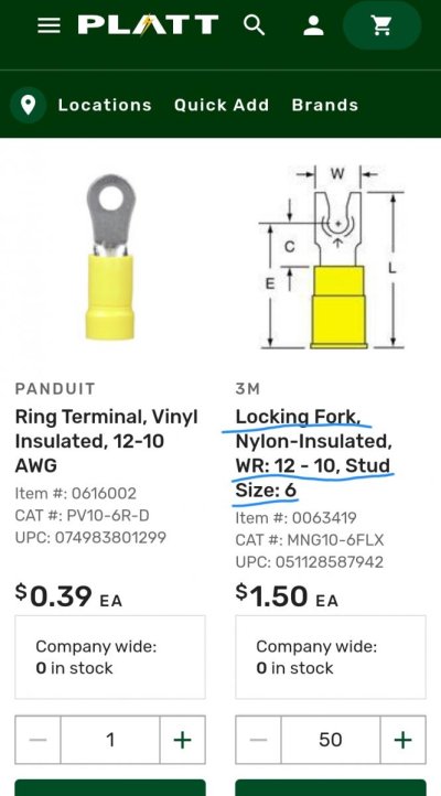
If you want the 3m lugs, platt sells them in smaller bags like 25 count. You might have to do a little searching on their website to find the locking forks.
https://www.platt.com/s/small-fork-ring-terminals?cat=1zi7fwy
 
Last edited:
Yes, the new green wire should be 12 Ga.

If memory serves me correctly the screws on the side terminals of a GFCI receptacle are #8s. They are nowhere near 1 1/2" long. Your definition accurately describes the receptacles two mounting screws.

You have the receptacle, measure them so you get the right stuff.

Both Mouser and Digi-key has stock in #8s and you can buy as little as one for $0.56 plus whatever other nuisance fee they charge. The link to either is right to the 3M website once you have selected a part.

https://www.3m.com/3M/en_US/p/d/v000323102/

This should not be this hard.
 
Thanks for the link
I thought the terminal screw size was standard so should be easy to search. but it was not directly available online or I don't have the buzz word.
last night I was about to measure the screw but realized it's designed not to be removed. I will use a caliper to measure the widest dia w/ thread on the screw to confirm the nominal dia.


Yes, the new green wire should be 12 Ga.

If memory serves me correctly the screws on the side terminals of a GFCI receptacle are #8s. They are nowhere near 1 1/2" long. Your definition accurately describes the receptacles two mounting screws.

You have the receptacle, measure them so you get the right stuff.

Both Mouser and Digi-key has stock in #8s and you can buy as little as one for $0.56 plus whatever other nuisance fee they charge. The link to either is right to the 3M website once you have selected a part.

https://www.3m.com/3M/en_US/p/d/v000323102/

This should not be this hard.
 
Last edited:
McMaster Carr has them in stock, ANY configuration you will need. Next day delivery. No large quantity purchase either.
 
It is not this hard! Post 2 gave the answer.
Variations of the answer followed. Is the 5 minute job completed and working?

the orders are still on the way
I'll work on it sometime next week
 
SteveK.

My comment WRT "This should not be this hard" specifically addressed only the acquisition of an ABYC compliant connector that actually fits a receptacle.

Lou's Post #2 was surely well intended but lacked specifics by only stating "proper crimped connectors" with no reference as to what they are.

paulga, it seems to me, doesn't know a lot on the subject and therefore is easily mislead, but is eager to do things right, and is willing to learn.
Isn't the collective wisdom of the Forum here to help other people learn, rather than be subjected to possibly snide comments like "Is the 5 minute job completed & working?"

This likely would be a 5 min. job if it was just a simple change out. But it may well not be as if you had read the thread, paulga appears to want to be ABYC compliant.

That means that the existing GFCI and teak block needs to be removed, the wire jacket restored, the new box assembled and mounted, the wires run, terminated and mounted on the new box and GFCI, then the GFCI mounted in the box and the door assembled and installed. Then energized and tested. All likely while on your knees in the ER.

I have the ER, I'll make a block from D.fir and mount it, and have all the other parts in stock. Plus, I have $100 USD that says you can't replace the whole thing, as stated above in your 5 min. time limit.
The winnings, we should both agree to send to paulga to help with his education.

Next time you are in the LM, bring your tools, your $100 USD, send me a DM and we can set it up!

Finally, to answer your question in Post #18, my understanding is ABCY requires that should the terminal screw work its way loose, the wire lug itself should not fall off of the screw, similar to what you would have with a ring lug. The goal is to not have an energized conductor loose enough to flop around.

The Captain Hook Lug you referenced I don't think satisfied ABYC as it can simply, like a forked lug, slide off should the screw become loose.
 
Wow, anyone else surprised this thread has 75 posts over 4 pages? Bit then I guess that pales in comparison to the collision and dismasting thread :)
 
SteveK.

My comment WRT "This should not be this hard" specifically addressed only the acquisition of an ABYC compliant connector that actually fits a receptacle.

Lou's Post #2 was surely well intended but lacked specifics by only stating "proper crimped connectors" with no reference as to what they are.

paulga, it seems to me, doesn't know a lot on the subject and therefore is easily mislead, but is eager to do things right, and is willing to learn.
Isn't the collective wisdom of the Forum here to help other people learn, rather than be subjected to possibly snide comments like "Is the 5 minute job completed & working?"

This likely would be a 5 min. job if it was just a simple change out. But it may well not be as if you had read the thread, paulga appears to want to be ABYC compliant.

That means that the existing GFCI and teak block needs to be removed, the wire jacket restored, the new box assembled and mounted, the wires run, terminated and mounted on the new box and GFCI, then the GFCI mounted in the box and the door assembled and installed. Then energized and tested. All likely while on your knees in the ER.

I have the ER, I'll make a block from D.fir and mount it, and have all the other parts in stock. Plus, I have $100 USD that says you can't replace the whole thing, as stated above in your 5 min. time limit.
The winnings, we should both agree to send to paulga to help with his education.

Next time you are in the LM, bring your tools, your $100 USD, send me a DM and we can set it up!

Finally, to answer your question in Post #18, my understanding is ABCY requires that should the terminal screw work its way loose, the wire lug itself should not fall off of the screw, similar to what you would have with a ring lug. The goal is to not have an energized conductor loose enough to flop around.

The Captain Hook Lug you referenced I don't think satisfied ABYC as it can simply, like a forked lug, slide off should the screw become loose.

Thanks for reiterating the work process.

I don't have a strong focus now on compliance with the regulatory code, only interested to see what is the proper way things get done here.

I'm shopping the locking fork connectors for the new grounding wire. The existing wires are already very short , likely I will have to use their current connectors as is. Understood this would fall short of the purpose of all the efforts covered in this thread to bring the whole GCFI outlet under compliance, it's still important to adopt the correct method. Then I would know what to do when adding another outlet later.
 
Thanks for the link
. . . I was about to measure the screw but realized it's designed not to be removed.

Paulga - these screws have the thread at their tips slightly deformed so that they cannot easily be completely removed. In spite of this, you can apply some more unscrewing force and successfully remove them in order to use ring type terminals.

Re-installing the screw is slightly difficult but quite doable.

You can chase the holes with a 8-32 or a 10-32 tap as well.

I use ring terminals and back out the screws.

If you use a hospital grade outlets (with the little green circle) the screws and terminals (usually) will be brass plated for hot and ground and nickel plated for line.
 
Last edited:
Thanks. They do have in stock.
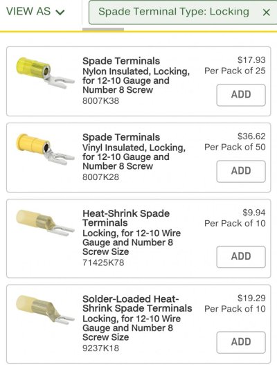
I found four sku. The last one is sold at a premium vs the other three. Any advantage does it come with?

Screenshot_2024-02-02-19-44-23-12_40deb401b9ffe8e1df2f1cc5ba480b12.jpg

McMaster Carr has them in stock, ANY configuration you will need. Next day delivery. No large quantity purchase either.
 
SteveK.

My comment WRT "This should not be this hard" specifically addressed only the acquisition of an ABYC compliant connector that actually fits a receptacle.

Lou's Post #2 was surely well intended but lacked specifics by only stating "proper crimped connectors" with no reference as to what they are.

paulga, it seems to me, doesn't know a lot on the subject and therefore is easily mislead, but is eager to do things right, and is willing to learn.
Isn't the collective wisdom of the Forum here to help other people learn, rather than be subjected to possibly snide comments like "Is the 5 minute job completed & working?"

This likely would be a 5 min. job if it was just a simple change out. But it may well not be as if you had read the thread, paulga appears to want to be ABYC compliant.

That means that the existing GFCI and teak block needs to be removed, the wire jacket restored, the new box assembled and mounted, the wires run, terminated and mounted on the new box and GFCI, then the GFCI mounted in the box and the door assembled and installed. Then energized and tested. All likely while on your knees in the ER.

I have the ER, I'll make a block from D.fir and mount it, and have all the other parts in stock. Plus, I have $100 USD that says you can't replace the whole thing, as stated above in your 5 min. time limit.
The winnings, we should both agree to send to paulga to help with his education.

Next time you are in the LM, bring your tools, your $100 USD, send me a DM and we can set it up!

Finally, to answer your question in Post #18, my understanding is ABCY requires that should the terminal screw work its way loose, the wire lug itself should not fall off of the screw, similar to what you would have with a ring lug. The goal is to not have an energized conductor loose enough to flop around.

The Captain Hook Lug you referenced I don't think satisfied ABYC as it can simply, like a forked lug, slide off should the screw become loose.
Maybe not 5 minutes, but in the time it took to read this rant the job would be done. Yes I have done it replacing a 30 year old regular plug to satisfy a surveyor quoting ABYC that it needs to be GFCI.

By now you should know I don't give a rats ass what ABYC has to say. Look at the picture Paulga posted of the GFCI. It is ancient and yet has worked until now without a marine label or ABYC type connectors. :banghead:
Yet I respect the opinion of others and have read the whole thread hoping to learn something of use. BTW, you have attributed a post or two to me that others suggested, but I accept that as I agree with the suggestions. :horse:
 
When I skippered a Yacht/sailboat on Sydney Harbour racing on Saturdays, having sailed on a similar yacht as forward hand under a less than complimentary skipper, I formed the opinion the performance of a person doing their very best at a task but struggling, was never improved by trenchant criticism mid task.
 
The purpose of a GFCI is to run the current to ground if the input current vs the output current have a discrepancy.

As far as my understanding goes, that is not accurate. The purpose of a GFCI is to detect a differential in current flow between Hot and Neutral of greater than approx 5 mA, and trip the interrupter within the GFCI device itself. Ground does not enter into this process.

If for some reason the outlet is only a two wire outlet, ie not grounded, that is a safety issue in and of itself. But not related to the functioning of a GFCI outlet.
 
Lou's Post #2 was surely well intended but lacked specifics by only stating "proper crimped connectors" with no reference as to what they are.

To my knowledge, and bare with me if I am wrong as I am not a surveyor, ABYC recommend usage of captive spade terminal. These are also called locking spade, captive fork and so on.

Some have kind of upward bend at the end to retain the screw, some have a kind of hole in the middle (not an eye).

Sorry but does not have the right terminology in English.

L
 
Well SteveK.

Unless you are in dire need of an intense remedial reading program, reading the 330 +/- words or 16 +/- sentences in my last post will take you way less than 5 min. which means that you have just shortened the time that you, yourself need to complete the task. Yet you still don't bite on the generous 5 min allowance............Why? It should be easy money for you! My offer is open, let me know when you come around.

I attributed one post to you, that would be post #72 where you said "Is the 5 minute job......." Are you saying that was not you?

I also responded to your post wherein you had referenced a C type connector and requested more information. That would be post #18. Again, not you?

So where exactly did I attribute to you a post that you did not make, but can accept? Be specific.
 
Luna, if Jay was here in the lower mainland I would have offered to meet and assist in person. I have nothing to prove to you. A simple problem has been blown out of proportion. Had he not asked a new GFCI would already be installed.
 
Thanks. They do have in stock.
I found four sku. The last one is sold at a premium vs the other three. Any advantage does it come with?

View attachment 145534

Yes, your wallet will be lighter after the purchase.

In theory, the advertised benefits include not needing a crimp tool and a greater resistance to pull out.

The reality is that they are an expensive and possibly risky solution to problems that do not exist.

Soldering wires is generally not recommended in boats because, at the joint, it creates a solid conductor from a stranded one, making the interface very subject to vibration and movement cracks and resulting failure.

For this reason, last time I looked at the ABYC guidelines they read, "Solder shall not be the sole means of mechanical connection in any circuit. If soldered, the connection shall be so located or supported as to minimize flexing of the conductor where the solder changes the flexible conductor into a solid conductor." And "If one is incapable of soldering correctly, or incapable of adequately supporting the wire being connected to a soldered connection, it is recommended that they do not solder."

I don't know if it has been specifically addressed since last time I looked, but I suspect it isn't entirely clear when, or if, these connectors are ABYC compliant. Concerns might be that the adequacy of the support may depend up the length, fit, adhesion, and rigidity of the tubing, which may be variable, as well as the specifics of the installation, including, for example, the mechanical load imposed by the wires upon the joint.

They might also leave it to tradesmenship w.r.t. whether or not it is good enough in a particular installation. Some things are necessarily left to skill and judgement. I dont know.

In any case, it isnt necessarily clear to me that they are, or are not, ABYC compliant in any particular use. I'd be a lot more likely to use them for tiny thin wires for which good crimp solutions are hard to find and for which the tubing walls are very thick and rigid as compared to the wire vs for thick wires, where the load imposable by the wire may more easily dominate the rigidity and support of the relatively thin tubing wall and for which crimp connectors are readily available and highly reliable.

Also, the solder used in these connectors is lower temperature than normal solder. I don't know how it's properties otherwise differ.

In any case, for what you are doing, I'd likely save the money on the expensive connectors and buy a good crimper: You'll be far ahead in time and money and utility in the long run. I think.
 
Last edited:
Luna, if Jay was here in the lower mainland I would have offered to meet and assist in person. I have nothing to prove to you. A simple problem has been blown out of proportion. Had he not asked a new GFCI would already be installed.

When I was new to reading the posts from Paulga I got a little exasperated too. But then, I realized he was truly trying to learn. Maybe he didn’t get the same type of exposure to this stuff that the rest of us did, and asks a lot of questions that an inexperienced person would.
Since we have a wealth of information stored in our heads, and we don’t even think about it when something needs done as we’ve done it countless times before, I think passing on the information should be done happily and thoroughly. As if I were teaching my children or grandchildren.
 
Back
Top Bottom