replace a gfci outlet

The friendliest place on the web for anyone who enjoys boating.
If you have answers, please help by responding to the unanswered posts.
It isn't considered acceptable because everything takes a belt and suspenders approach and allowing the improper device to plug in gets rid of the suspenders.

Yes, I know the logic and agree with it. All I said was that the perils, given the differences in current ratings are small.

There are many of examples where in the Marine world people are allowed to plug things in that have the potential to overload the supply circuit, yet they seem to marketed to the unwashed with impunity.
The dockside CB is your only protection.

Here is one of my favourite examples. Don't pull your hair out.

https://www.marinco.com/-/media/inriver/S15-504_SPEC.pdf?modified=20191030132534

Yeah. It would have been impossible for them to put a breaker inline, right? Maybe even a gfci?


I
 
Thanks the decoding these terms

What it means is that, that particular panel mounted circuit breaker, if it is still performing like originally specified will allow a continuous current of 20 Amps to flow out its output terminal without tripping. At 25 Amps it will trip quickly.
At an increasing load of anything between 20 and 25 Amps it will trip at progressively shorter periods of time as defined by the TD 3 designation, which if you can find it would define by way of some graph what the Time Delay to trip is, based on the actual current. This Time Delay info is normally not important to us boaters.

This seems to indicate that the breaker is capable, but you need to ensure the wiring and any connections are also capable. If you have UL 1426 boat cable then for a 20 Amp load undermost circumstances 14Ga. wire is acceptable, but I am more comfortable with using 12 Ga.
 
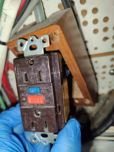
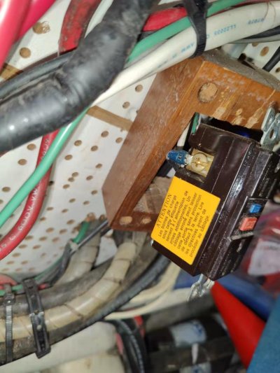
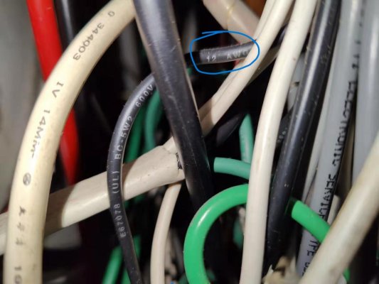
I didn't get enough clearance to see the letters on the wire jacket, but the existing outlet is 15A. Only the LINE portion is wired, with some kind of spade connectors already in place, so it should be a direct swap

question is, is it necessary to use a 15A marine quality gfci outlet, or will the 20A residential one work fine?

Image_20240129221734.jpg

Image_20240129221743.jpg

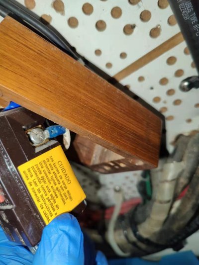
Image_20240129221749.jpg

While I agree with the statement to seek professional help if you are unsure of what you are doing, changing out a GFCI protected receptacle is usually not difficult.

To answer your Post #1 questions:

The second set of holes on the back side (which are not used on a boat) are used with solid wire to extend the circuit further to other ordinary receptacles that will also be protected by the GFCI receptacle. In effect, if the GFCI is in the first receptacle, all other receptacles on that circuit are also protected. If the GFCI receptacle is the only or last one in the circuit, only it is protected.

Always electrically connect the green (grounding) wires from the line and load to the grounding screw on the GFCI. In addition, if the electrical box in the wall is metallic you need to connect it to the this grounding screw just like the instructions show, but do not use any wire nuts ever. One way to do this is to mount the line and load's green wire along with a short piece of green wire to the metallic box's grounding screw. The other end of this short green wire goes to the GFCI's ground screw.

Although the folded fork connector (referred to upthread) may well be ABCY acceptable, my understanding is that a locking fork connector is also acceptable. In my experience the folded forks are not quite long enough as to not be in conflict with the oversized headed screws (normally used to clamp bare wire) that are used in the receptacle's side terminals.
In addition, the folded fork connectors make it impossible to get 2 connectors on one terminal should you have an extended circuit.

Buy only good quality terminals, something like these.

https://www.hubbell.com/burndy/en/P...cking-Fork-Terminal-For-12---10-AWG/p/2024163

Strictly speaking it may be that the use of a 20 Amp rated GFCI receptacle (where one blade of the plug is spun 90º) on a 15 Amp breaker protected circuit is prohibited, the peril here is almost unmeasurable. If you did manage to find some appliance that has a 20 Amp plug attached and powered it with a 15 Amp circuit, provided that everything is in good shape, the breaker trips.
That being said, I recommend that if you are to use this 20 Amp rated GFCI ensure that the panel mounted breaker and all of the wiring in the circuit is also rated for 20 Amps.

Please don't take this the wrong way, but your questions in Post #12 reveal that you should really learn a lot more about the electrical distribution system in your boat before you undertake any further work.
 
I would use a 15Amp marine grade outlet. If you were replacing a 15amp fuse you would not use a 20 amp fuse, right? Will it likely burn down your boat? I doubt it. But why intentionally do that?
 
Ok, with the wrapper on the load terminals of the original failed GFCI, it must be the only or the last receptacle on the circuit.

Those are fork not spade terminals and should be changed to locking fork terminals, but that is somewhat hard to argue when they likely outlived the GFCI they are attached to. Yes, the code says they are no good, so change them. Ok, it's not a code, forgive me please.

There is no metallic box in the picture which is yet another code (see above) violation. Ditch the fancy teak block and install a surface mounted exterior grade box c/w a spring loaded and gasketed door for the actual plug in ports, so you can sleep well at night and pass your next survey, should the surveyor ever stumble across this electrical outlet.

Insofar as the need to install a marine quality (is there such a thing?) 120V GFCI receptacle versus a common residential GFCI, of which there are many, I can only say I have never bought a GFCI produced by Marinco, Hubbell or others that profess to be marine grade and have had excellent service from Leviton or Eaton's products which litter my boat for now well over 15 years.

The question of a 15 Amp or 20 Amp GFCI receptacle can only be answered once you know for certain the wire gage and connection integrity. That determination rests with you.
 
I would use a 15Amp marine grade outlet. If you were replacing a 15amp fuse you would not use a 20 amp fuse, right? Will it likely burn down your boat? I doubt it. But why intentionally do that?

What is a "marine grade" outlet?
 
a side question, do you use this type of crimper to claw the wire into this fork connector, or a much higher gauge DC wire into other types of lug

Ok, with the wrapper on the load terminals of the original failed GFCI, it must be the only or the last receptacle on the circuit.

Those are fork not spade terminals and should be changed to locking fork terminals, but that is somewhat hard to argue when they likely outlived the GFCI they are attached to. Yes, the code says they are no good, so change them. Ok, it's not a code, forgive me please.

There is no metallic box in the picture which is yet another code (see above) violation. Ditch the fancy teak block and install a surface mounted exterior grade box c/w a spring loaded and gasketed door for the actual plug in ports, so you can sleep well at night and pass your next survey, should the surveyor ever stumble across this electrical outlet.

Insofar as the need to install a marine quality (is there such a thing?) 120V GFCI receptacle versus a common residential GFCI, of which there are many, I can only say I have never bought a GFCI produced by Marinco, Hubbell or others that profess to be marine grade and have had excellent service from Leviton or Eaton's products which litter my boat for now well over 15 years.

The question of a 15 Amp or 20 Amp GFCI receptacle can only be answered once you know for certain the wire gage and connection integrity. That determination rests with you.
 
I have zero issue using a 20 amp receptacle on a 15 amp circuit. The 15 amp breaker would protect the wire and trip if too large of a load is connected. It’s not the outlets job to protect the wiring, and a higher amp rating on the outlet means a more robust construction.
We’re not on Paulgas boat, so we don’t know the particulars of the situation. Is the wire long enough to change the ends and put the outlet in a box? Hopefully so, but if not, I’ve seen worse.
 
What is a "marine grade" outlet?

What a silly question! It is the one packaged and sold at a marine price.

Like THIS one
Love the comment made by one purchaser.
I purchased this thinking there was some reason that Marinco would sell a 'marine' GFCI receptacle. What I received was a LEVITON 7599-W receptacle in a Marinco package. This is a $12 item found at almost any hardware store that Marinco is selling with a more than 300% markup. The item does not match the picture on this site, nor what is shown on the Marinco site. Out of curiosity I called WestMarine and one other store, and they verified that it is a LEVITON 7599 in the package.

I wrote to the ABYC (American Boat and Yacht Council), and their response was that there is no distinction between GFCI units used on boats or in houses.

In short, DO NOT buy this Marinco item. Buy the LEVITON 7599-W instead (same thing) and save $30:
 
Disclaimer: Everything on your boat (and mine) is suspect. These were built in boat yards in Taiwan by craftsman when ABYC was not strictly adhered to. The boats also had previous owners, such as yourself, that do not FULLY understand ABYC electrical code, but have great intentions.
I also had those lovely teak outlet boxes. I have since replaced every one on my boat up to code. I have also seen outlets with GFCI with only 2 wires going to them???? Do not assume that they are "grounded", especially on a boat. What is ground on a boat, right?

The purpose of a GFCI is to run the current to ground if the input current vs the output current have a discrepancy. Ex: A short circuit inside of a metal component where the housing is now electrically charged and you become the path to ground. 10 amps going into the outlet and 0 returning because now you are the ground.
In a 2 wire GFCI outlet, a regular "circuit tester" will not show protected.

Replacing wires or connectors is also a concern. Think of defining where the weakest link will occur? Smallest item will get the hottest. Old wire gets brittle and breaks very easy.
 
so the term marine quality stresses more on compliance with the codes. I wouldn't buy a marinco that somehow packages a gfci outlet to multiple of its true price

What a silly question! It is the one packaged and sold at a marine price.

Like THIS one
Love the comment made by one purchaser.
 
the black wire is 12g, so it's rated for 20amp (14g for 15A). Even if it's 14g, my understanding is the 20amp gfci should still work, as long as its work load is far below 20A, there is no risk of overheat. I'll use the 20A gfci with the existing fork connectors.

could you post a link to the surface mounted exterior electrical box?


Image_20240130220624.jpg


Ok, with the wrapper on the load terminals of the original failed GFCI, it must be the only or the last receptacle on the circuit.

Those are fork not spade terminals and should be changed to locking fork terminals, but that is somewhat hard to argue when they likely outlived the GFCI they are attached to. Yes, the code says they are no good, so change them. Ok, it's not a code, forgive me please.

There is no metallic box in the picture which is yet another code (see above) violation. Ditch the fancy teak block and install a surface mounted exterior grade box c/w a spring loaded and gasketed door for the actual plug in ports, so you can sleep well at night and pass your next survey, should the surveyor ever stumble across this electrical outlet.

Insofar as the need to install a marine quality (is there such a thing?) 120V GFCI receptacle versus a common residential GFCI, of which there are many, I can only say I have never bought a GFCI produced by Marinco, Hubbell or others that profess to be marine grade and have had excellent service from Leviton or Eaton's products which litter my boat for now well over 15 years.

The question of a 15 Amp or 20 Amp GFCI receptacle can only be answered once you know for certain the wire gage and connection integrity. That determination rests with you.
 
One other complication is if you still have a modified sine wave inverter some GFCIs are not compatible and may "trip at a current that is too high (unsafe condition) or too low (nuisance trips), or may have difficulty resetting under some conditions", according to Xantrex. See Xantrex Help Center

When I last looked at this before switching to a true sine wave inverter, buying the marine ones didn't necessarily help with that either it really was just a crap shoot.

I didn't observe this during my one week cruise. the period underway will be limited comparing with she staying at slip, so the calling for a pure sine wave invertor is not urgent
 
Insofar as which crimping tool to get, first you need to figure out what brand of uninsulated, insulated, and heat shrinked terminals you are generally going to use, be it Thomas & Betts, 3m, FTZ, Ancor, or someone else and then buy their tool to crimp the terminals. The Amazon hydraulic crimper for 12 Gage to 2/0 wire terminals is not the proper tool. Buy a tool that is made by the terminal maker (that looks like a set of pliers) and is made for the terminals you are going to use. Its nice when things match!

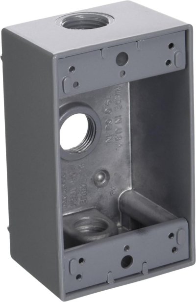
WRT the exterior box, try this,

https://www.amazon.ca/Greenfield-B2...ce+mount+electrical+box&qid=1706672472&sr=8-7

From there you should be able to find a cover with a spring loaded and gasketed door. Hubbell for sure makes one that HD sells. Go there and look.
You will also need at least one strain relief compression fitting that screws into one of the holes in the box to ensure that the wires are safely lead into the box.
 
Greetings,
Ms. p. As to crimpers...As I suggested in my post (#14), a good ratchet style is my preference.
The "crimper" option on the wire stripper is NOT acceptable IMO.
 
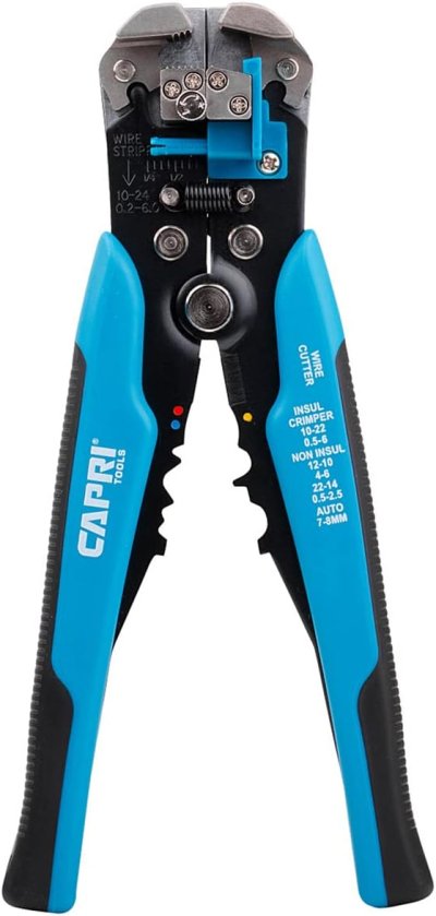
I got a Capri wire stripper that can crimp insulated and non-insulated terminals from 22-10 AWG. is it sufficient for the type of connectors on gfci?

View attachment 145470

That style of crimper where the crimp dies are in the grip area, are the least favorable to use. Only as a last resort if no other crimper is available.
There’s a staggering number of crimpers and dies available now, and I have at least ten of them set up for different products and an air powered bench model and a big assortment of dies.
But, on the boat, I carry an old school klein 1005. It does 95% of what I need. https://www.amazon.com/Klein-Tools-...Vk5Of91Fc0FYR432rpsmFMUsWgRoCDpgQAvD_BwE&th=1

If I’m doing something special, I’ll bring in a special crimper.
 
Thanks.
I was able to find the box and the door , but didn't see what a strain relief compression fitting is. Could you add link?

Also, does adding the metal box make it necessary to change the existing connectors?

818VvZn0F4L._AC_SL1500_.jpg

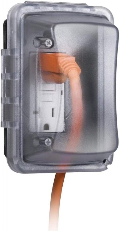
71Bn-1+v1QL._AC_SL1500_.jpg


Insofar as which crimping tool to get, first you need to figure out what brand of uninsulated, insulated, and heat shrinked terminals you are generally going to use, be it Thomas & Betts, 3m, FTZ, Ancor, or someone else and then buy their tool to crimp the terminals. The Amazon hydraulic crimper for 12 Gage to 2/0 wire terminals is not the proper tool. Buy a tool that is made by the terminal maker (that looks like a set of pliers) and is made for the terminals you are going to use. Its nice when things match!

WRT the exterior box, try this,

https://www.amazon.ca/Greenfield-B2...ce+mount+electrical+box&qid=1706672472&sr=8-7

From there you should be able to find a cover with a spring loaded and gasketed door. Hubbell for sure makes one that HD sells. Go there and look.
You will also need at least one strain relief compression fitting that screws into one of the holes in the box to ensure that the wires are safely lead into the box.
 
Last edited:
Home Depot up here in the frozen north of Canada sells a strain relief kit made by Carlon. HD in the US of A likely stocks a similar kit.

The different bushing are for various cable sizes and shapes. If your 3 wires are no longer in the outer jacket where they enter the box, (quite possible) use the best snug fitting bushing in the kit. The goal is for the bushing to grip the 3 wires to restrict their movement and attempt to make things drip proof. Wire entry into the box from below allows for physics to work in your favour.

Here is the HD link with some pictures and a bit of a video.

https://www.homedepot.ca/product/ca...IyvN6TVK72ZaHfp7zKxoCqP8QAvD_BwE&gclsrc=aw.ds

The box itself should come with plugs to fill the unused threaded holes, use them.

Also, now that you are going to use a metal box, it must have the green (grounding) wire connected to it, no exceptions.

WRT the door, if the receptacle is going to be largely unused, this door does a better job of keeping the moisture out of the actual connections as when unused, as it is sealed by a gasketed door.

https://www.homedepot.ca/product/re...al-white-cover-for-gfci-receptacle/1000407160

Doing it right takes time & $.
 
Thanks for filling the details.
It looks like the carlon srtc-050 is only sold in Canada. Hopefully this strain relief fitting is close enough


Home Depot up here in the frozen north of Canada sells a strain relief kit made by Carlon. HD in the US of A likely stocks a similar kit.

The different bushing are for various cable sizes and shapes. If your 3 wires are no longer in the outer jacket where they enter the box, (quite possible) use the best snug fitting bushing in the kit. The goal is for the bushing to grip the 3 wires to restrict their movement and attempt to make things drip proof. Wire entry into the box from below allows for physics to work in your favour.

Here is the HD link with some pictures and a bit of a video.

https://www.homedepot.ca/product/ca...IyvN6TVK72ZaHfp7zKxoCqP8QAvD_BwE&gclsrc=aw.ds

The box itself should come with plugs to fill the unused threaded holes, use them.

Also, now that you are going to use a metal box, it must have the green (grounding) wire connected to it, no exceptions.

WRT the door, if the receptacle is going to be largely unused, this door does a better job of keeping the moisture out of the actual connections as when unused, as it is sealed by a gasketed door.

https://www.homedepot.ca/product/re...al-white-cover-for-gfci-receptacle/1000407160

Doing it right takes time & $.
 
It came to my mind this setup requires adding a short green wire, so two connectors are needed. could you recommend what connectors to use? Or just winding around the screws clockwise?

Home Depot up here in the frozen north of Canada sells a strain relief kit made by Carlon. HD in the US of A likely stocks a similar kit.

The different bushing are for various cable sizes and shapes. If your 3 wires are no longer in the outer jacket where they enter the box, (quite possible) use the best snug fitting bushing in the kit. The goal is for the bushing to grip the 3 wires to restrict their movement and attempt to make things drip proof. Wire entry into the box from below allows for physics to work in your favour.

Here is the HD link with some pictures and a bit of a video.

https://www.homedepot.ca/product/ca...IyvN6TVK72ZaHfp7zKxoCqP8QAvD_BwE&gclsrc=aw.ds

The box itself should come with plugs to fill the unused threaded holes, use them.

Also, now that you are going to use a metal box, it must have the green (grounding) wire connected to it, no exceptions.

WRT the door, if the receptacle is going to be largely unused, this door does a better job of keeping the moisture out of the actual connections as when unused, as it is sealed by a gasketed door.

https://www.homedepot.ca/product/re...al-white-cover-for-gfci-receptacle/1000407160

Doing it right takes time & $.
 
Crimper is the secondary function of the Capri 20012 tool. Its primary purpose is to strip

That style of crimper where the crimp dies are in the grip area, are the least favorable to use. Only as a last resort if no other crimper is available.
There’s a staggering number of crimpers and dies available now, and I have at least ten of them set up for different products and an air powered bench model and a big assortment of dies.
But, on the boat, I carry an old school klein 1005. It does 95% of what I need. https://www.amazon.com/Klein-Tools-...Vk5Of91Fc0FYR432rpsmFMUsWgRoCDpgQAvD_BwE&th=1

If I’m doing something special, I’ll bring in a special crimper.
 
Last edited:
As I mentioned in one of my earlier post a locking fork connector is the one I use at a GFCI terminal rather than a folded fork connector as the large heads of the screws in the GFCI's terminals do not fit in the space provided in any folded fork connector that I have ever tried. Locking fork connectors I believe are also ABYC compliant.

Here is some info, lots of other good brands exist, buy only good named brand American made ones as they can potentially carry 2400 watts due to your 20 Amp circuit. You don't want to cheap out here. Leave Alibaba alone for electrical stuff.

https://www.3m.com/3M/en_US/p/c/ele...ergy/electrical-construction-and-maintenance/

The first one shown on the attached link is not a locking fork connector, ignore it.
 
Thanks for filling the details.
It looks like the carlon srtc-050 is only sold in Canada. Hopefully this strain relief fitting is close enough

Not only is that fitting outrageously expensive, its designed to be assembled into a pipe fitting using 1/2" NPT threads, note there is no locking nut on the mount side. Really unusual thereby justifying the expense.
It won't thread into you selected box correctly.

Find another one the right thread size for your box with the locking nut. To make the rubber gripping insert fit your 3 individual wires you may have to make them as round as you can using a couple layers of heat shrink.
 
Crimper is the secondary function of the Capri 20012 tool. Its primary purpose is to strip

Crimping is too critical of a task to use a tool that is not primarily designed for crimping.
 
Thanks for the 3M link, I sse the nuances in the fork opening. I read post #49 again, the connectors have a choice from uninsulated, insulated and heat shrinked, and further from a slew of makes within each category

Are most of the connectors in that 3M link considered both insulated with heat shrink?

As I mentioned in one of my earlier post a locking fork connector is the one I use at a GFCI terminal rather than a folded fork connector as the large heads of the screws in the GFCI's terminals do not fit in the space provided in any folded fork connector that I have ever tried. Locking fork connectors I believe are also ABYC compliant.

Here is some info, lots of other good brands exist, buy only good named brand American made ones as they can potentially carry 2400 watts due to your 20 Amp circuit. You don't want to cheap out here. Leave Alibaba alone for electrical stuff.

https://www.3m.com/3M/en_US/p/c/ele...ergy/electrical-construction-and-maintenance/

The first one shown on the attached link is not a locking fork connector, ignore it.
 

Latest posts

Back
Top Bottom