JDCAVE
Guru
- Joined
- Apr 3, 2011
- Messages
- 2,912
- Location
- Canada
- Vessel Name
- Phoenix Hunter
- Vessel Make
- Kadey Krogen 42 (1985)
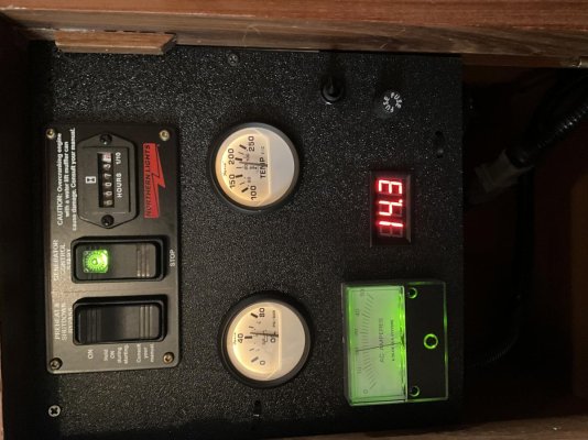
My Northern Lights Genny came with the Series 1-B Control Panel, which is pretty basic. There are no diagnostics coming from the unit. The Series 3 panels has oil pressure, engine water temperature and DC voltage output. This panel is nearly $1,100 USD.
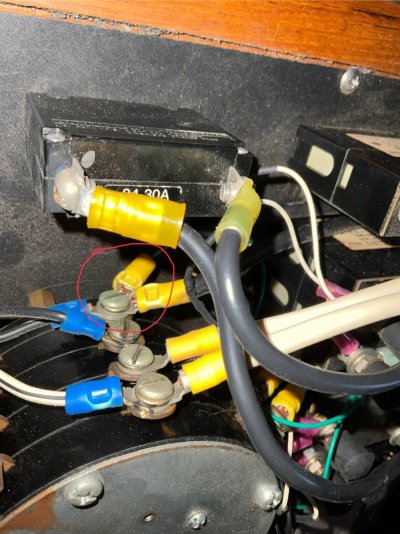
The wiring harness for the control panel is 8 wires if I remember correctly. I had to extend it at the time of installation. Would it be possible to tap into these wires and connect to VDO, Fario or equivalent gauges? Has anyone experience with this and have information on which wire provides what data? Also, would the DC alternator information be useful?
Jim