Need Help Wiring my New Alt and Reg:)

The friendliest place on the web for anyone who enjoys boating.
If you have answers, please help by responding to the unanswered posts.

Taras

Senior Member
Joined
Jan 11, 2008
Messages
405
Vessel Make
Currently Boatless
Hey All,
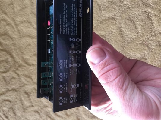
I have purchased a new 200 amp 24 volt alternator (Off brand) and the Balmar Max Charge MC-624 external regulator.
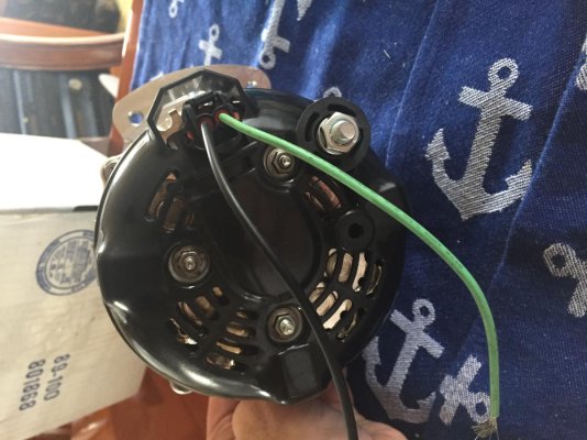
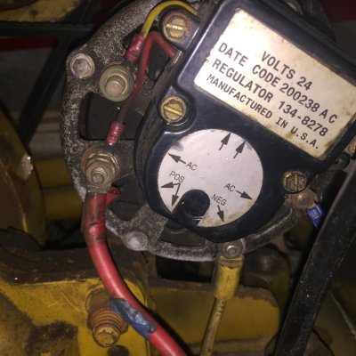
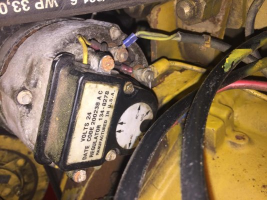
I have attached the photos below of the old Alt and the New Alt, along with the Balmar reg.
I could really use some help in connecting this thing properly.
Can anyone help me to understand the complete way to wire these up?
I plan to upgrade the output wire to the battery bank along with a 300 amp in-line fuse.
Your help would be so appreciated,
Steve
Old Alt pic 1.jpg

Old Alt pic 2.jpg

New Alternator.jpg

Max Charge Reg MC 624.jpg
 
First you will need to program the regulator. Marinehowto.com has a step by step guide how to do that. Basically hook the regulator up to a battery on a work bench and go through it one by one setting. Much easier to do before installing it. I bought the 10’ wiring harness for the regulator so that I could mount it outside the engine room and have a service loop so that if I decide to change parameters it will be easy to do rather than standing on my head in the ER. Good luck. Also Balmar tech support was very helpful.
 
Question about the alternator. You say Off Brand? Model number? Manufacturer?

Is it set up for or modified for an external regulator?

I suspect looking at the back , the picture, that it is a stock internal regulator alternator. I suspect it does not have provision for external regulation. Without that provision you can wreck the alternator, the regulator and/or the batteries.

Do you have a diagram for the alternator connections? A better, closer photo showing any labels or stampings/markings of the terminals present. If so post them.

I have studied the manual enough, I think, that the regulator needs that extra external regulation terminal for proper operation.

I may be all wet but I think you need to look again.

--Wire #1 Brown from ign sw. to provide turn on power to the regulator.

--wire # 2 Red from the alternator main output or ,better, direct to the battery so the regulator can read the actual voltage. It also likely provides the power for the variable voltage and power to the rotor so the regulator can control the alternator.

--wire # 3 Orange is for a tachometer drive signal and will maintain a tiny voltage to ensure the tach gets a signal eliminating the frequent problems when the alternator shuts down which then kill the signal and the tachometer then quits giving a revoulution count.

--wire #4 Blue Is the actual voltage control that the regulator feeds to the rotor. THe regulator varies this voltage to vary the amperage output from the alternator in line with the program you have set for the battery type.

--wires 5 - 11 You supply. THe other terminals, are simply for accessories, alternator and battery temperatures for protection and a lamp to indicate the regulator is working. The temps probes are a GOOD idea.

--wire # 12 is the regulator ground to be done at the alternator. Often there is a dedicated ground screw but if not then back out on of the case bolts and secure it to that bolt.

I won't say all alternators can be modified but most can be by an alternator/starter shop or by a handy owner. THe internal regulator will need to be removed or defeated and bypassed, some wiring changes made, maybe a new post for the BLUE wire to the brushes, some insulator bushings made and so on.

You need to plan on upgrading both the Positive output wire AND the Negative return wire or you may have trouble. Engine block grounds are not always as good as they would appear. Good enough for intermittent use while cranking and the light loads from other equipment but I would question for long term, high output use. The negative can be secured to the alternator mounting bolts unless it has a dedicated ground terminal.
 
Last edited:
Another TF educational post (for me). Following
 
Question about the alternator. You say Off Brand? Model number? Manufacturer?

Is it set up for or modified for an external regulator?

I suspect looking at the back , the picture, that it is a stock internal regulator alternator. I suspect it does not have provision for external regulation. Without that provision you can wreck the alternator, the regulator and/or the batteries.

Do you have a diagram for the alternator connections? A better, closer photo showing any labels or stampings/markings of the terminals present. If so post them.

I have studied the manual enough, I think, that the regulator needs that extra external regulation terminal for proper operation.

I may be all wet but I think you need to look again.

--Wire #1 Brown from ign sw. to provide turn on power to the regulator.

--wire # 2 Red from the alternator main output or ,better, direct to the battery so the regulator can read the actual voltage. It also likely provides the power for the variable voltage and power to the rotor so the regulator can control the alternator.

--wire # 3 Orange is for a tachometer drive signal and will maintain a tiny voltage to ensure the tach gets a signal eliminating the frequent problems when the alternator shuts down which then kill the signal and the tachometer then quits giving a revoulution count.

--wire #4 Blue Is the actual voltage control that the regulator feeds to the rotor. THe regulator varies this voltage to vary the amperage output from the alternator in line with the program you have set for the battery type.

--wires 5 - 11 You supply. THe other terminals, are simply for accessories, alternator and battery temperatures for protection and a lamp to indicate the regulator is working. The temps probes are a GOOD idea.

--wire # 12 is the regulator ground to be done at the alternator. Often there is a dedicated ground screw but if not then back out on of the case bolts and secure it to that bolt.

I won't say all alternators can be modified but most can be by an alternator/starter shop or by a handy owner. THe internal regulator will need to be removed or defeated and bypassed, some wiring changes made, maybe a new post for the BLUE wire to the brushes, some insulator bushings made and so on.

You need to plan on upgrading both the Positive output wire AND the Negative return wire or you may have trouble. Engine block grounds are not always as good as they would appear. Good enough for intermittent use while cranking and the light loads from other equipment but I would question for long term, high output use. The negative can be secured to the alternator mounting bolts unless it has a dedicated ground terminal.

Thank you for your response. Here are more specifics:
New Alternator Specifics:
*The issue I have is I purchased the Alternator about 2 years ago and don't remember the manufacturer and it did not come with a manual :( . All I remember is its built for 24v and was bench tested to 200 amps. Very heavy unit.
*This is an externally regulated Alternator.
*Looks like it "might" be "self excited". I don't see a field wire connection on the new alternator??
*The post with the nut is obviously the output to the battery bank.
*The black wire is probably negative.
*The green wire could be "stator"? (note the stock alternator's green stator wire). Is there a way to check to see if this is indeed the Stator wire?

Balmar Regulator:
*All connections clearly marked on the side.

Thanks for all thoughts:)
 
This is just a guess, but if it's truly set up for external regulation, then the black and green pigtails I would guess are the field wires. But is it both field connections, or is one pole connected internally and the other brought out on one of the two wires? I can't tell looking at it.


One of the wires could be the stator wire for a tachometer. Maybe. But I also see three smaller terminals, all of which could be stator outputs available for use.


The larger terminal post is likely the positive output.


The output negative is probably the alternator frame since I don't see any corresponding negative post.


Sorry I can't offer more answers.
 
Thank you for your response. Here are more specifics:
New Alternator Specifics:
*The issue I have is I purchased the Alternator about 2 years ago and don't remember the manufacturer and it did not come with a manual . All I remember is its built for 24v and was bench tested to 200 amps. Very heavy unit.

******* Can you not go back to the shop or vendor and ask them about the two wires in the plug and the question about the external regulator hookup. Telephone, Email, website? Are there ANY labels of any kind on the alternator? Are there any embossings or stampings near each post and terminal. Any alternator I have seen identifies each terminal since mfgr. to mfgr. the layouts may be similar but NOT the same.**********

*This is an externally regulated Alternator.
*******I don't see any dedicated terminal for the regulator to attach to.
Ok, then you MAY be able to test the leads using an ohmmeter. Attach the leads, on to ground [the case] and the other lead to one of the wires. Then reverse the leads on the same wire. If it is the control wire then there should be LOW AND SIMILAR ohms both ways. THe circuit is from the terminal [wire] to a brush, through the field/rotor windings , back to the other brush and then to ground, the case. I seriously doubt the field/rotor brush circuit will be grounded externally. If not the first wire then test the other wire.
This SHOULD indicate the control circuit. If you get any other reading then be vary carefull.

A Further test may be done. Attach a voltmeter's leads to the big battery terminal and the case for ground set on low voltage scale. Use a D cell and hook it up to the wire you now THINK is the regulator input. The other end of the battery to be grounded. This is not polarity sensitive. The alternator, for this purpose won't care. Then spin she rotor shaft by hand. Even wrap a few feet of small stuff [rope] around the shaft using it to pull and thus spin the shaft. You should be able to get enough speed to create a voltage.. There should be a momentary voltage show before the battery croaks. Or if you have an adjustable power supply attach it per the battery and set it for very low volts [1 or 2] and spin the shaft watching the V meter for voltage. The alternator must be secured for you to be able to reliably/safely spin the shaft. **********


*Looks like it "might" be "self excited".
******* Any self excitement is simply a result of the residual magnetism between the spinning rotor poles and the stator poles but has nothing to do with the regulator operation. Many alternators have such poor residual magnetism they are reluctant to start without an external feed or revving way up momentarily. THe regulator will over ride it for control.*******

*The post with the nut is obviously the output to the battery bank.
********* Agreed, that is the big nut in the upper R.H. corner.*********

*The black wire is probably negative.
********* Unlikely as it is far to small and I will guess the pins in the plug are also to small so would burn up in short order at any high level of output.. I was thinking the main power output.

AHA OR

if you mean it is negative for the external regulator , maybe but that could be tested as I started to describe above to determine if indeed one of those two wires are part of the ext. reg. setup. Do the tests above but of no joy then connect the ohmmeter between the two wires and if they are both for the external regulator then you should get the same low ohms reading including switching the leads. If this is in fact the case then you can use one of the case bolts as a ground for the reg. Spin the shaft and you might see a bit of ohms bounce.**********

*The green wire could be "stator"? (note the stock alternator's green stator wire). Is there a way to check to see if this is indeed the Stator wire?
******** Possible but I would not count on it without testing as above or asking********

Balmar Regulator:
*All connections clearly marked on the side.
******** Yes, I saw that and also went to Balmars site to get the PDF instructions.*******


My last suggestion is if there are still any questions then take the new alternator to an alternator/starter shop and ask them to open it up and FIND out for sure what is what.
 
Last edited:
Ok,
So went to Alternator repair shop today in L.A. They were not helpful. So I called Balmar. Wow, these guys are great. I worked with Tim in the tech department. I must have spent an hour with him. Sent him all the photos. Then they had me take the back cover plate off the new alternator and we identified where the Stator connector was (it wasn't connected so I had to solder a new wire on to the stud inside). Balmar was able to identify the following:
1) Stator wire had to be created by soldering on a wire from the inside of the alt.
2) Black wire is Case Ground
3) Green wire is "Field"
4) Big output post with the nut on it is obviously positive output to the battery bank.
*Now I should be all good to go. Wiring it up tomorrow:)
Will report back to how everything works and will of course program the external regulator before I fire everything up.
Can't say enough good things about the tech support I got from Balmar.
Thanks to everyone here for the help as well!!
Steve
 
I had very good dealings with Balmar when I went a bit off-label and put a big alternator on my little sailboat motor. They provided top notch advice and arranged for a local shop to make some mods for me on mounts and pulleys.

I've got a new XT kit waiting to go in my new boat.
 

Latest posts

Back
Top Bottom