MPPT sizing

The friendliest place on the web for anyone who enjoys boating.
If you have answers, please help by responding to the unanswered posts.
I have 4 panels @ 100W each so I plan to do 2+2 series, then parrallel them. There does not seem to be guidance to do one over the other for better results.
 
Hi fellow solar boaters
This is what I plan to do with my solar install!!
I will have 2 200 watt panels wired in series to an 8 gauge solar cable. From here the cable will travel approximately 25 feet to a space in the salon about 5 feet above the house battery bank.
An on/off switch will be installed before MPPT still using 8 gauge wire and after the MPPT will go to 6 gauge to another on/off switch. After that to the battery via a 6 gauge wire to a 60 amp fuse attached to positive battery post.
The on/off switches and MPPT controller will be in easily accessible location in the salon just incase stuff hits the fan.
Any improvement suggestions other than grammar plaese feel free to advise.
Thanks again everyone
J.T.
 
I have 4 panels @ 100W each so I plan to do 2+2 series, then parrallel them. There does not seem to be guidance to do one over the other for better results.

The usual wisdom on series /parallel is that if you have shading issues wire parallel. Of not, go series.
 
Hi fellow solar boaters
This is what I plan to do with my solar install!!
I will have 2 200 watt panels wired in series to an 8 gauge solar cable. From here the cable will travel approximately 25 feet to a space in the salon about 5 feet above the house battery bank.
An on/off switch will be installed before MPPT still using 8 gauge wire and after the MPPT will go to 6 gauge to another on/off switch. After that to the battery via a 6 gauge wire to a 60 amp fuse attached to positive battery post.
The on/off switches and MPPT controller will be in easily accessible location in the salon just incase stuff hits the fan.
Any improvement suggestions other than grammar plaese feel free to advise.
Thanks again everyone
J.T.

If you have a battery monitor/ amp hour counter, be sure to land the negative lead on the right side of the shunt or the amps won’t be counted.
 
If you wire in parallel you need to install a blocking diode so you loose .7 volts an d this is gone 100% of the time.

My panels are in parallel and have been that way 5 years. I didn't install any diodes and everything has been just fine.
 
MPPT Sizing

My mfgr: Victron Energy
My vendor: emarineinc.com

I am quite certain the model numbers of the Victron MPPT are made up of the
Maximum Voltage on the input side from Solar PVs | the Maximum output in Amps that one will ever possibly see coming from that controller.

So, my Mppt 150|35 can have a max number of 7x - 19 VDC PV Panels hooked in series to safely operate, and I will never see more than 35 Amps of charge current coming out of it.

Similarly my MPPT 100|20 can have 5x 19 VDC PV Panels hooked up in series, and I will never see more than 20 Amps of charge current coming out of it.

I currently have 4x 19 volt/200 watt panels. While my MPPT 150|35 can handle all of them hooked up in series, one of the panels is on the bow. A very long series circuit was not advised to have all of them hooked up to one controller. So, the one on the bow got its own controller, and the ones on the stern have their larger controller... I still have room for more there should I want to go there later on!

In reality, one never accomplishes the total max current the controller is theoretically able to produce. But the number helps in selecting the right fuse or circuit breaker for after the controller. (The max voltage IN should never be exceeded by design.)

I recommend you select a vendor who will give you plenty of pre-sales "engineering" so you get the guidance you need from an authoritative source. e.g. +1 for emarineinc.com in my experience
Marc Doheny there was very helpful. 954-764-9339

Side note:
While I have read "some people on the Internet" advocate for a separate Solar Controller for each PV panel. I also know that the MPPT panels won't start to produce until there is about 17 volts (5 "extra" volts) coming in before they wake up in the morning. SO, having 2 or more PV panels in series makes that 17 volt starting point happen earlier in the day. Consult with your expert/vendor to be certain for your design.
 
Last edited:
MPPT Sizing

My mfgr: Victron Energy
My vendor: emarineinc.com

I am quite certain the model numbers of the Victron MPPT are made up of the
Maximum Voltage on the input side from Solar PVs | the Maximum output in Amps that one will ever possibly see coming from that controller.

So, my Mppt 150|35 can have a max number of 7x - 19 VDC PV Panels hooked in series to safely operate, and I will never see more than 35 Amps of charge current coming out of it.

Similarly my MPPT 100|20 can have 5x 19 VDC PV Panels hooked up in series, and I will never see more than 20 Amps of charge current coming out of it.

I currently have 4x 19 volt/200 watt panels. While my MPPT 150|35 can handle all of them hooked up in series, one of the panels is on the bow. A very long series circuit was not advised to have all of them hooked up to one controller. So, the one on the bow got its own controller, and the ones on the stern have their larger controller... I still have room for more there should I want to go there later on!

In reality, one never accomplishes the total max current the controller is theoretically able to produce. But the number helps in selecting the right fuse or circuit breaker for after the controller. (The max voltage IN should never be exceeded by design.)

I recommend you select a vendor who will give you plenty of pre-sales "engineering" so you get the guidance you need from an authoritative source. e.g. +1 for emarineinc.com in my experience
Marc Doheny there was very helpful. 954-764-9339

Side note:
While I have read "some people on the Internet" advocate for a separate Solar Controller for each PV panel. I also know that the MPPT panels won't start to produce until there is about 17 volts (5 "extra" volts) coming in before they wake up in the morning. SO, having 2 or more PV panels in series makes that 17 volt starting point happen earlier in the day. Consult with your expert/vendor to be certain for your design.


Be careful about those voltage calculations. See post #8. You need to use at least 125% of the open circuit voltage to allow for temp and exposure variations. Over voltage to the MPPT controller can (probably will) be catastrophic.
 
Mr. Twisted Tree
It seems to be volts is the big issue here. MPPT will control amp output. Is there a maximum amps a line with 22.5 VOC can carry? It seems to be the biggest concern wit these solar systems. On my battery fusing I'm going with maximum amp output of the MPPT plus 10 at the battery bank connection(50 +10 = 60).Hopefully I'm in the right ball park here. Any suggestions here would be appreciated. I have no paperwork on the ordered components yet because they are in transit.
Cheers fellow solar Babies
J.T.
 
The fuse is sized to protect the wire. So if you are planning a 60 amp fuse, the wire should be sized to handle that load.
So, you’re looking at #6 or #4 depending on the wires insulation rating.
The voltage doesn’t really come into play, as I can’t imagine you’ll be putting in wire that isn’t rated for 22.5 volts. That’s an unusual volt callout btw, what’s your system voltage?
I think 22.5 or thereabouts is doorbell tranformer voltage
 
BMarler
The voltage on my boat is 12 VDC. The 200 watt bi facial panels are rated at 22.5 VOC with max power output at 11 amps each. I would like to have fuses close to MPPT controller but the battery fuse would be 5 feet away from battery. Any suggestions or ideas ?
J.T.
 
BMarler
The voltage on my boat is 12 VDC. The 200 watt bi facial panels are rated at 22.5 VOC with max power output at 11 amps each. I would like to have fuses close to MPPT controller but the battery fuse would be 5 feet away from battery. Any suggestions or ideas ?
J.T.

when i did mine, i built a little panel to hold the mppt controllers, and circuit breakers in and out of the controllers. that way, i could turn off either the power from the panels, or the power to the batteries, or both. those breakers were sized to the panels, mppt controllers, and the wire to hook them up matched the breakers. that setup connects to the batteries via the pilothouse buss.
i have two 385 watt panels at around 40 volts or so, with #10 wire to the breakers. also #10 from the controllers to the output breakers, and then a short run to the pilothouse buss. the pilothouse buss has a 2/0 feed to the batteries and a fuse at the battery buss to protect the 2/0 wire.
it's more than was necessary, but i like being able to isolate everything. there might be a slight voltage drop by not bringing the mppt output directly to the battery buss, but it would be extremely small.

i think the rule for fuses is about 6 or 12 inches from the battery, so keep that as short as possible. i will fudge that distance if it makes a better installation, but then provide chafe protection for the wire. it sounds like the controllers are pretty close to the batteries, so #10 wire should be ok. from the panels to the controllers, i don't know what length the run is, but 200 watts at 20 volts is only 10 amps (or 11 according to the panel manufacturer), so to keep it simple, i'd probably just use #10 for everything. this is assuming you have only one panel per (30 amp?) mppt controller. if there are multiples, the wire may need upsized.
 
oops, i just read your previous post where it mentioned 50 plus 10 amps. you must have a bigger controller and multiple panels. list the number of panels, and the size of the controller, as well as the distance from the panels to the controller, and the controller to the batteries. then we can size the wire and fuses properly.
 
BMarler
I'll be using two 200 watt bi facial panels that have a VOC of 22.5 and max amp input of 11 amps per panel. I've got a victron MPPT 100/50. Planning on wiring in series to keep cable size between panels and MPPT so there is no more than 2% loss between them. My run will be approximately 21 feet from panels to controller and 8 feet to battery.
Thanks for any info everyone
J.T.


I'll jump in with one answer on this.


I think you said earlier that your bifacial panels can produce up to 15% more than rated. And as I have commented earlier, to account for temp and exposure variations, you should assume 25% more production. So I would combine to 140% of rated values.


In series your panels will be 140% of 11A, or 15.4A. So the cabling and fusing needs to be able to handle that. 12ga wires is a good starting point.


For power loss in the solar cable, I would size the cable run for a 3% loss ideally, and no more than 5%. You will need to use one of the loss calculators based on your cable length to determine if and how much the wire gauge needs to be greater than 12ga to meet those loss objectives. But for this calculation I would use the max power point for the panels since that's where you will see the greatest power loss. In fringe conditions you will get more power loss, but it's much less of a concern since it's the fringes. So use Vmp (voltage, max power point) x2 for two panels in series, and Imp (current, max power point).


On the battery side, figure the current based on 140% of rated power, so 140% x 200W x 2, or 560W. Max current will be when the batteries are low, so use 12V. That gives 46.6A into the batteries. You will need at least a 50A breaker, and 6 ga wire. But also run the % loss numbers to see if you need to go even larger with the wire size. I think you said this run was relatively short, so 6ga may work out OK from a loss perspective too.
 
Mr. Twisted Tree and all!!!
Going to a #4 wire for 8 feet won't break the pirates chest!! So going with a 60 amp fuse between the battery bank and the MPPT controller should be sufficient? Wow!! I was thinking of connecting 600 watts to the 100/50 MPPT controller and I guess I had a very good chance of smoking it in ideal conditions. This thread has saved me at least $200 in controller plus every thing that could go wrong on both sides.
Mr. Twisted Tree and BMarler and all

Thankyou again,This has been a great learning experience in the solar world J.T.

I think you have a good handle on it now. The only issue you might have with #4 is fitting it into the terminals on the controller. A crimp ferrule or pin can really be helpful.

See these: https://www.te.com/usa-en/products/...es-pin-terminals-wire-tabs.html?tab=pgp-story
 
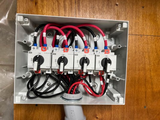
We used the following for breakers between the panels and controllers, and between the controllers and the main battery bus:

https://www.amazon.com/dp/B09B3K5PJ...FUZCNKC4&psc=0&ref_=list_c_wl_lv_ov_lig_dp_it

https://www.amazon.com/gp/product/B09H4WNK3S/ref=ppx_yo_dt_b_asin_title_o04_s00?ie=UTF8&th=1

This gave us a nice clean setup with breakers that can be used for circuit protection, or manually tripped to isolate the panels, or controllers.
We have 8 each, 360 watt Silfab one face panels, and 8 each Victron 100/30 MPPT Smart controllers
They've been running since May 2022 with no problems, just periodic cleaning of the panels:dance::D
 
MPPT Sizing

BMarler and Mr. Twisted Tree
I was hoping to go with a Blue sea product for a on/off switch between the panels and MPPT controller but they all seem to max out at 48 volts. I can use it from MPPT to battery being 12 volts but the panels are 22.5 volts each. Any more suggestions ?

Thanks J.T.
 
I had a similar issue when I had my panel built. I think I ended up with Carling breakers.

Peter
 
Also check out AltEStore.com. They have a wide variety of breakers rated at 60ADC and 125VDC at reasonable prices. Most are DIN rail mount, but some might be panel mount.


I have also used these IMO disconnect switches a couple of times where voltages can exceed 125V. They are bit expensive, but much less than many alternatives. Again, DIN rail mounted, shown here in an ABB enclosure.
 

Attachments

  • PCH_2023-10-17_08-02_5236.jpg
    PCH_2023-10-17_08-02_5236.jpg
    159.6 KB · Views: 11
BMarler and Mr. Twisted Tree
I was hoping to go with a Blue sea product for a on/off switch between the panels and MPPT controller but they all seem to max out at 48 volts. I can use it from MPPT to battery being 12 volts but the panels are 22.5 volts each. Any more suggestions ?

Thanks J.T.

Have a look at the Amazon link slowgoesit posted. Scroll down and you’ll see some other options. Some are 110 volt rated, some are 500 volt rated. All are dc rated at that voltage, din mount, and designed for solar systems. I used something very similar on my installation.
 
MPPT Sizing

Mr. Twisted Tree and All
Are these type of DIN breakers good by ABYC standards or is this a grey area? Would I need a single or dbl pull breaker? Mr. Twisted Tree, what type or brand of switch did you use? I'm so close with the 48 volt blue sea but with your formula I'm about 10% shy. I'd like to have for an Extra switch option if I expand array with a additional panels and MPPT controller.
Thanks everyone. Looks like I'm on the final leg of this design.
 
While using single pole switching will disconnect the source/load, if you want true isolation you need to disconnect both sides. Not saying one way is better than another, just saying.

I see those switches are indeed two pole.
 

Latest posts

Back
Top Bottom