The Magnus effect

The friendliest place on the web for anyone who enjoys boating.
If you have answers, please help by responding to the unanswered posts.
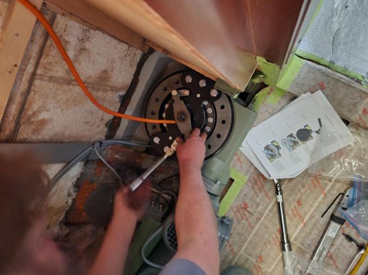
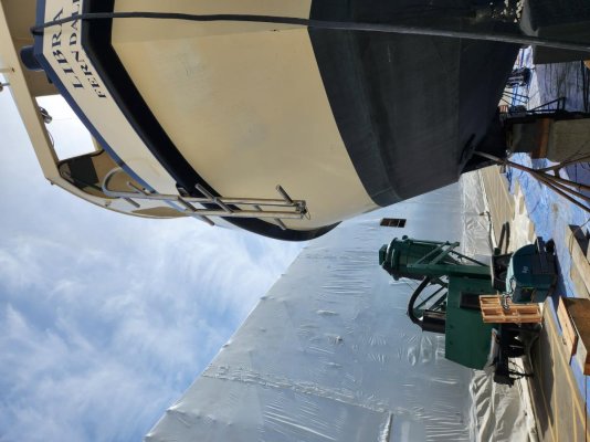
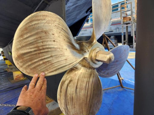
No photos yet but I am just back from two days in the yard on this project.
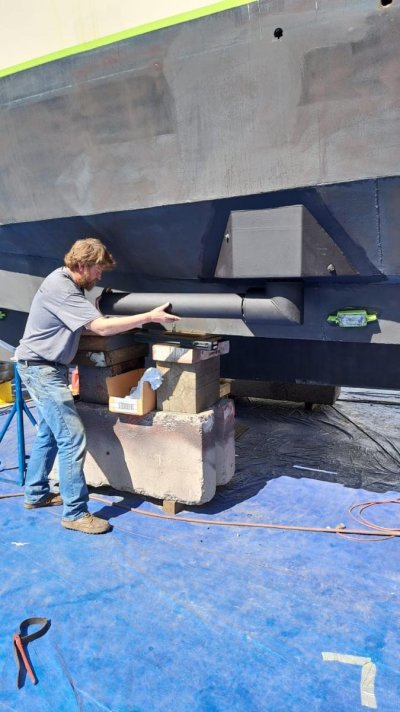
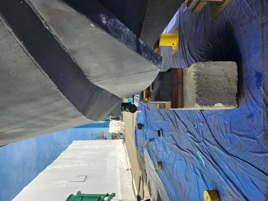
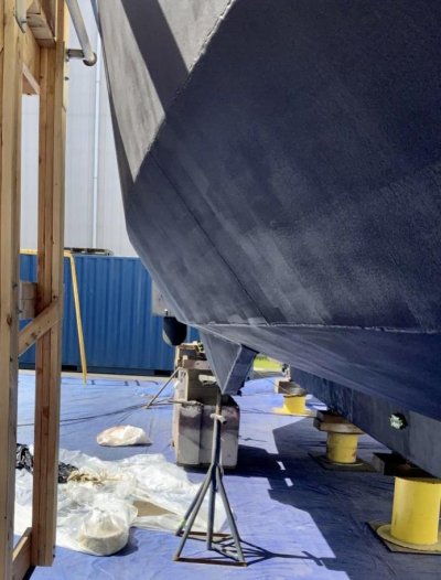
We spent the time working on placement and workplan for the stabilizer bushing installs and on a number of other projects that I am having the yard do.
This was my first look at the equipment that was shipped from Holland and my first real experience with this shipyard.

For now, I will just say that I am quite impressed with both, and I have not previously ever made a comment like that in regard to a shipyard experience.
Fingers crossed that this ends as happily as it has started.

DMS will send an engineer from Holland once the bushing and foundation are complete, and the cable is run. I spoke with her several times during this visit and believe that is also an excellent resource. Final connection, commissioning, and sea trial is projected to be the week of May 2.
This is quite exciting for me.
For the locals following this thread, the plan is to have DMS demo this install/my boat at the Anacortes show in May.
Next update late next week.
 
KW any further news?

Yes, here is the update photo essay. Both myself and the project manager were away all week last week, but we are back at it.
After much deliberation and head scratching, we had made a decision on placement before I left in order to maximize function and minimize interference both inside and outside of the boat.
The holes in the hull have been cut and bushings welded in. The stabilizer hardware above and below attach to this bushing that penetrates the hull.
Cabling has been run but not terminated until next week. A foundation to secure the bushings will be fabricated over the next couple of days. The DMS engineer will arrive for final torques and terminations on Monday of next week and we expect to be on sea trial by Thursday or Friday of next week.

Photos are:
Hole in hull from outside
Hole from inside
Cutout showing hull thickness with a quarter in my fingers
Bushing tacked thru hull
Example of bushing welded
Cabling in floor of helm station
Monitor and cutout in the dash for it
 

Attachments

  • 4FE06B5C-A370-45B9-982D-B812832CA5CD.jpg
    4FE06B5C-A370-45B9-982D-B812832CA5CD.jpg
    191.1 KB · Views: 32
  • 7BD8A898-6162-4299-B84C-80FF5CDEE0FF.jpg
    7BD8A898-6162-4299-B84C-80FF5CDEE0FF.jpg
    137.9 KB · Views: 34
  • C983DEF7-484A-46E3-B131-61B6839AE438.jpg
    C983DEF7-484A-46E3-B131-61B6839AE438.jpg
    96.3 KB · Views: 34
  • 8D22E587-575F-4FB6-A89C-6EED8C495CE7.jpg
    8D22E587-575F-4FB6-A89C-6EED8C495CE7.jpg
    106 KB · Views: 34
  • 035F23DD-E808-4F3E-833D-2EEF2F48645B.jpg
    035F23DD-E808-4F3E-833D-2EEF2F48645B.jpg
    56 KB · Views: 40
  • 94CA6E02-4DB6-46B2-9D27-6450BE78B1DB.jpg
    94CA6E02-4DB6-46B2-9D27-6450BE78B1DB.jpg
    197.8 KB · Views: 30
  • 816253D1-0B12-4EE9-B69A-60DD4C024F68.jpg
    816253D1-0B12-4EE9-B69A-60DD4C024F68.jpg
    143.6 KB · Views: 28
All photos loaded sideways so you will get a better orientation to the project if you look at them from 90 degrees clockwise.
 
What?? No comments on those welds in post #33?
I think they are beautiful! I am prone to be inspired by highly skilled trades people.
 
A stack of dimes is always a sight to see. Stick or wire?
 
What?? No comments on those welds in post #33?
I think they are beautiful! I am prone to be inspired by highly skilled trades people.

as a fabricator myself, i feel kinda bad for not giving a thumbs up to that. you can bet though, if they were crappy welds there would have been some mention...
 
as a fabricator myself, i feel kinda bad for not giving a thumbs up to that. you can bet though, if they were crappy welds there would have been some mention...

This is obviously mild steel welding. I have several projects going on at the same time that involve stainless fabrication and will try to get some photos of those on another trip to the yard. Equally inspiring for sure.
This is the first boat yard I have visited where I have taken the view that the skill level among the trades and the prices charged were pretty well in line with each other. More commonly cost has been richer than skill level.
Not here.
 
DMS Holland is expanding their US footprint, they have a place in Ft. Lauderdale and recently added Lamb's Yacht Center as a qualified service yard in Jacksonville, FL. I happened to be there when the first 10" cylinder was being inserted into the bottom of a Selene and chatted with DMS about it. They seem very customer-oriented and I'd expect they will become more common, especially in the full displacement market. The engineering makes sense. Around the 18 ton or less range a single magnus rotor is supposed to be sufficient.
 
What?? No comments on those welds in post #33?
I think they are beautiful! I am prone to be inspired by highly skilled trades people.


Funny you should ask; that is the first thing that I noticed when scanning the pics. Welds like that are great sign that the fabrication overall will be high quality. I'm a bit of a fabrication nerd since I once was involved in motorsports where the engineering and metal fab work was art.


The project looks good and I would be happy with the work shown for sure. Looking forward to seeing the installation and how you like the performance when complete.
 
YouTube

Scheduled to go in the water tomorrow for sea trial. Video short linked and some recent photos.
 

Attachments

  • 9D93847F-B72E-437C-9254-AEA056DD52DA.jpg
    9D93847F-B72E-437C-9254-AEA056DD52DA.jpg
    193.9 KB · Views: 16
  • 62C335E4-0D08-4FD8-A015-0472281B0C4B.jpg
    62C335E4-0D08-4FD8-A015-0472281B0C4B.jpg
    129.5 KB · Views: 18
  • 184B7A4F-1DEB-48C3-BA3C-A35AE1D67159.jpg
    184B7A4F-1DEB-48C3-BA3C-A35AE1D67159.jpg
    115.2 KB · Views: 21
  • C1B52DEB-C188-49C1-A9CF-359E5A8FC1F1.jpg
    C1B52DEB-C188-49C1-A9CF-359E5A8FC1F1.jpg
    150 KB · Views: 19
No judgement, just thinking that while the shown welded-on hull 'pod' is expedient,
a gently curved addition would produce less turbulence and drag even if it was a
bit longer. Skilled fabricators surely would be able to manage such a thing.
 
No judgement, just thinking that while the shown welded-on hull 'pod' is expedient,
a gently curved addition would produce less turbulence and drag even if it was a
bit longer. Skilled fabricators surely would be able to manage such a thing.

KY,
It is a bit hard to show a picture that shows the perspective, but I have added one here to see if it helps.
These are skilled fabricators that have built these pods for the long sonar tubes for military and the fishing fleet where drag is also important. The fore and aft leading edges of the pod are tapered to the hull at 45*.
I am confident that drag will not be a significant issue and that flow down the hull will not be disrupted significantly enough to concern me.
 

Attachments

  • C8C800FE-6504-4425-870F-922943EAD3C4.jpg
    C8C800FE-6504-4425-870F-922943EAD3C4.jpg
    83.5 KB · Views: 19
Last edited by a moderator:
KY,
It is a bit hard to show a picture that shows the perspective, but I have added one here to see if it helps.
These are skilled fabricators that have built these pods for the long sonar tubes for military and the fishing fleet where drag is also important. The fore and aft leading edges of the pod are tapered to the hull at 45*.
I am confident that drag will not be a significant issue and that flow down the hull will not be disrupted significantly enough to concern me.

Understood.
In my boating experience which includes sailboats, any and all projections tended
to be curved and even streamlined if feasible. Large heavy trawlers would clearly
get less benefit from doing that than lighter displacement sailboats or motorsailers.
 
I will report tomorrow the change in speed in flat water compared to prior where I have a very good baseline. With stabs parked, I am expecting a loss of 0.15 knots.
 
Bill,

Do you have an estimate of power required to operate the system underway? I watched there video and understand how the system works, but was wondering what the hydraulic HP requirement was for spinning the tubes.

For your application, is the pump on the generator to give you stabilization at anchor as well, or on the main engine for use only while underway?

It looks very interesting.

Ted

Great questions, Ted, and highlights why I chose this system over alternatives.
1. Takes less room resulting in less interference inside the boat than fins or gyro.
2. Less drag when parked than fins.
3. Less power required and runs in AC, not fluid power. I will run off the inverter so will not need to have the generator running except when I need to top up the bank and then will be running under full charger load.
The max power that can flow to the system when activating the system (coming out of park position to extended position plus spinning the rotors) will be 2800 watts. In moderate sea state but activated, it should pull 1100-1200 watts. In big sea states up to 1500 watts. That is 12.5 amps per hour of operation at 230 volts and 62 amps at 24 volts(my bank) so with a limit of 30 discharge I should be able to run 5 hours between generator runs and then run the genny for an hour.

:thumb:

Outstanding! The educational video was for a larger vessel with a hydraulic system. I just couldn't fathom having to run the generator for stabilization at anchor.

While they're not going to get installed on my boat (fuel tanks in the way), my 220 amp house bank alternator and inverter would easily power them.

Waiting for the SEAtrial report.

Ted

Ted, I don't think they work at anchor, unless you are in a current of 3 knots or more!
 
Ted, I don't think they work at anchor, unless you are in a current of 3 knots or more!

From what I saw in the tutorial video, the tubes sweep for and aft in addition to rotating while at anchor, or so they claim.


Ted
 
Welds can be a tradesman`s signature. In a case about a failed truck trailer turntable, the turntable mfr could not only say it had been modified post manufacture, but also that those welds not done by anyone at the mfr. And could identify who in the shop did the welds of the unmolested parts of the turntable.
 
From what I saw in the tutorial video, the tubes sweep for and aft in addition to rotating while at anchor, or so they claim.


Ted

The company that manufactured my system is named DMS Magnus Master, different than the one in your video. DMS is all electric as far as I know and while they may have a system for stabilizing at rest, this one that I installed does not. For the Magnus effect to work, water must be flowing over the rotor at least at 3 knots speed. That is the minimum you would need to swing the rotor at rest and then alternate direction quickly.

Now back to tradesmen. This photo will not show it well, but I had them make me a stainless boarding ladder since I had no way to reboard the vessel should I fall off. What a nice piece of work!
Photo of boarding ladder below and I gratuitously threw one in of the 38" wheel just prepped for a coat of PropSpeed.
 

Attachments

  • boarding ladder.jpg
    boarding ladder.jpg
    117.1 KB · Views: 32
  • wheel.jpg
    wheel.jpg
    148.3 KB · Views: 19
Ordering if DMS has development software to minimize pitch. Could have two pairs of rotors placed as far forward and aft as retracted state allows. This would permit diminishing roll, pitch and corkscrewing. Be the bees knees

Also when not being perturbed get all 4 developing lift to decrease wetted surface. That might even increase efficiency.

On a boat with trim tabs you could also potentially install faster tab actuators and integrate that into the system to reduce pitching. I've found on some boats, even just keeping the tabs down slightly all the time reduces pitching, as the extra lift at the stern and resulting downward pressure on the bow adds some damping to the pitching motion, making it a bit slower, smoother, and smaller in amplitude.
 
Oh man......
Sea trial day has been a very good day for LIBRA and her crew.
These things are as advertised.
I do not have a video for you though I think the DMS engineer, and the Platypus project manager likely got them. I may get my hands on one and will post if I do.
I cannot comment much other than to say that the degree to which these little rotors and 1200 wats of AC power can move this 136K# boat around is much greater that what makes sense to me. Peak draw was 1740 watts and normal power draw while under way seemed to be around 1150 watts when we caused a big roll.
We did induced roll from the rotors and induced roll from dramatic oversteering using the fast joystick. Rotors off was hanging on with some banging going on and rotors on was smooth. Certainly 70% or more reduction.
We did not find any serious sea state in the Strait of Juan de Fuca today but will on Saturday likely and I will report again.
We ran single rotor and both rotors. The engineer could give us 15° of roll in what seemed like less than a second induced by the rotor.

I think this will always seem strange to me.
 
Last edited by a moderator:
Addendum:

Regarding drag/speed loss. I am not sure I can detect any from baseline so likely not nothing, but nothing I could hang my hat on when rotors were parked parallel.
With rotors out and turning I may have lost a tenth or two from baseline it seems like. Not more than that.
 
Eagerly waiting for video of these inaction…
 
Addendum:

Regarding drag/speed loss. I am not sure I can detect any from baseline so likely not nothing, but nothing I could hang my hat on when rotors were parked parallel.
With rotors out and turning I may have lost a tenth or two from baseline it seems like. Not more than that.

It would be interesting to know the increased fuel consumption value (producing electricity for the rotors + drag) as a percentage of normal fuel consumption, to stabilize the boat.

Ted
 

Latest posts

Back
Top Bottom