replace a gfci outlet

The friendliest place on the web for anyone who enjoys boating.
If you have answers, please help by responding to the unanswered posts.
Thanks.
since the grounding wire is not critical, I would use that 12g yellow wire as the new grounding wire, keeping other terminals unchanged.


Yes, there is spiral loom on the visible wires. It could be such that inside the wall and along the rest of the wire's route, there exists the factory outer jacket that groups these 3 wires together. This type of outer jacketed wire is commonly used as it speeds up installation.

The individual wire's size and temp rating should be marked on this outer jacket and/or the individual wires. You just need to find the markings!

Without a doubt, the gauge and temp. rating matter!

Inside the metal box, the new grounding wire from box to the GFCI should be the size of the supply conductors, although if this was a terrestrial based installation the wire can be one size smaller and even uninsulated.
I don't know if ABYC allows those two things, as it's just easier to use the same green wire.
 
Thanks. I will see this weekend.

My opinion:

To answer your question - It is not good practice. You will have higher risk of a poor connection. You may have to resort to this when at sea to achieve a fix, but should never do this on land.

If you do crimp a yellow terminal onto a 14awg wire you should apply lots of crimping force and then really pull hard on the wire - trying to pull it out of the terminal - to ensure that the terminal is really holding the wire.

Another trick is to fold the wire strands double before inserting into the terminal.
 
Steve, in large measure, Yes.

First, regarding your Table link, only the first Table actually applies here as it's defining the ampacity. I checked a few instances off of your table and they appear to be the same as my older (20 yrs.) information, with the exception of your table for 60º C in the ER column is blank, mine has numbers and the bundled conductor defintions are a bit different.

Your's show bundling groups of one, and then, two to three, while mine show groups of, no more than two and then, three. The remaining bundling conditions appear to be the same. So in effect, the change is only in the two wire bundled condition which now has it's ampacity reduced by 30% just like my three wire condition. Poor thing, I wonder what it did?

This effects the exact condition that I cited earlier, but until Paulga returns with some definitive info. on his wire, I'm not going to revise what was said. Should I comment further to Paulga, I will you these reduced tables to err on the side of caution. Thanks.

I did not check every number on this first table but they look largely the same, and you can find the numbers that I cited on your table quite easily.


The remaining tables which are for 12V & 24V systems, are for voltage drop which usually is not important in a 120V ac branch circuit as the loads are low and the branches are usually short. Regardless, even if it did apply it has nothing to do with the ampacity of the existing conductor, which is the question.

BTW, although these 4 tables imply dc (by way of the familiar 12V & 24V) the ac's voltage drop is the same as the dc's. You would be surprised how much you use low volt ac in normal life.

I tried a few conditions using your Calculator and got my numbers as well, except for the grouping issue defined above. Again not an exhaustive review, but they loosely look the same. You do need to switch the calculator to Ampacity mode, as it wakes up in Voltage Drop.

Another useful tool, thanks.
 
Thanks.
since the grounding wire is not critical, I would use that 12g yellow wire as the new grounding wire, keeping other terminals unchanged.

In the 32V or higher world of ac, the green grounding wire is the most critical wire there is in the circuit, as it could save your life. Nothing is more precious!

As evidence of this, it is the only conductor in the entire distribution system that it is prohibited from be switched or have any over current protection. Switches or OCPs can and do fail open or closed.

Exceptions do exist when selecting different power supplies, there you need to switch the grounding conductor to the new supply.

Do yourself and the next boat owner a favour, at least wrap the yellow wire with green electrical tape and make sure you install it correctly.
 
Yellow is the new black for DC negative power.
Hey, Maybe that is why it was changed to avoid confusion as 120AC is also black (and red).
Good advise to either not use it for a green ground or cover it with green tape.
 
i checked two more gfci outlets both have blue terminals, and the wires behind them are thinner, so maybe 14g wires for these two outlets.

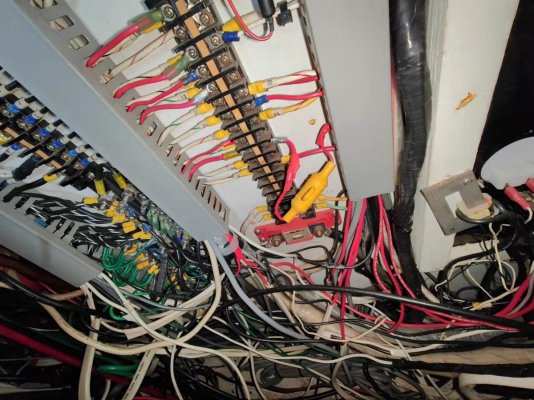
I traced the wires for the ER outlet to a hole in the ceiling below the service panel. Then I looked into the back of the panel and had to take a pause here. it requires more knowledge to comb through these wires.

Image_20240205224314.jpg

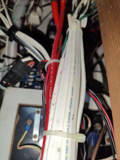
I did notice some sections of outer jacket mark "10 awg", and the wires are similarly thick as that outlet's in ER. if a 10g wire is tucked into a 14-16g terminal, the installer must have cut some strands. Does this reduce the max current load of the outlet?

Image_20240205224319.jpg
Understanding that this Engine Room routed circuit is supplied by 20 Amp breaker, you really need to confirm what is the gage of the wire and the wire's insulation (jacket) temperature rating. Both are normally written on the outer jacket that envelopes the 3 wires resulting in a flat cable. You can always measure the copper wire itself, but you cannot determine the temperature rating (usually between 60º C. & 200º C.). This temperature rating has a big part to play in the current carrying capacity (called Ampacity) of the wire.

It gets worse, the Ampacity is also effected by how many current carrying wires are bundled together along the route to the breaker. If we were to say there are 6 bundled together the Ampacity of 14 Gage wire with an insulation temperature rating of 60º C. has an Ampacity of just 7 Amps, if the insulation's temperature rating is 105º C. (common UL1426 boat cable) Ampacity is up by 240% to 17 Amps. Isn't life grand!

If all of the above condition stay the same except that there are only 2 wires bundled together (Green wires don't count) the respective values are 11 and 29 Amps.

I suspect that the existing wires are indeed 14 Gage, (outside insulation diameter is not a good indicator for gage as too many insulation types exist) and appear to be type 2 stranded (19 individual wires in the insulation) which is acceptable for general purpose wire aboard. I also suspect that the insulation's temperature rating is at best 75º C. as I don't recall ever seeing type 2 stranded wire with a higher rating unless the insulation is silicone based. Although there are lots of things that I've never seen.

The fact that the individual copper conductors are not tin plated has no role in the electrical performance of the wire, but does play a small role in it's survivability.

What to do? You really need to determine the wire size and temp.rating. Without that we are all guessing. Good luck digging the wire out.
 
Lou

Although I acknowledge that the table you referenced (it suffers from the same grouping issue that was identified earlier) indicates that 14 Gage wire, clad with 105º C. rated insulation, can according to Ancor safely conduct the loads on 15 or 20 Amp protected circuit, there is no indication that Paulga's existing wire is Ancor's wire.

Paulga's picture clearly shows the copper is not tin plated, Ancor's typically is tin plated.
The pictures also seem to show that the individual strands are not consistent with the size (.010" diameter) and quantity (14 gage has 41 strands) used in Ancor's UL 1426 boat cable.

All of this does not necessarily mean that the existing wire (likely not Ancor's) cannot be used, but does mean that Paulga, in order to comply with ABYC needs to determine what are the specs. on the existing wire and insulation, to see if it can safely used.

To assign an Ampacity to an unknown wire, to me seems fraught with peril.
 
I think it is such that you intended to write "No where in the instruction does does it say not to remove the screws." rather than the "not say" that you wrote. If so, you're right the instructions do not prohibit you from removing the screws, but they do say that the warranty is void if opened, abused, altered in any manner, etc.
I would think forcing out captive screws, thereby damaging important threads would be considered at least a couple of the above no-nos.

Have you ever seen a Marine Rated (meaning bearing the coveted UL Marine Mark) GFCI? I have not, got a link?

The issue does not stop just with GFCI's, how about Marine Rated duplex receptacles, wall switches or Edison lamp sockets? Got any of those?

Even Hubbell's canary yellow self proclaimed Marine Grade HBL53CM62 would not meet the UL Spec as is it not restricted to use with only stranded copper conductors. Solid wire is Ok as well.

https://hubbellcdn.com/specsheet/WIRING_HBL53CM62_spec.pdf

Agree.

And no, I haven't seen any marine rated receptacles. Seems like a solution for a non-problem.

Just pointing out the complexity of overlapping and adopted standards of different organizations.

Sometimes understanding the reasons for and consequences of the rule are as (or more) important as the actual rule. Sometimes, it's just not as easy as "Just follow the rules."

I think the OP has received both good guidance on the standards, as well as from actual member's experience for a solution to his "problem." It also seems as though the OP is trying to practice due diligence.
 
I finally got time to complete it yesterday. it was not a breeze as I thought, and the figuring out process while kneeling down for extended period inside the corner of the ER was rather painful.

it took several trial and error, at some point I had to reverse and start over, to fit the wires through a heat shrink tubing, strain relief fitting, and to rearrange the wires to be out of the way of the gfci unit. the unique location of the elec box and the shortened lengths of wires added to the difficulty.

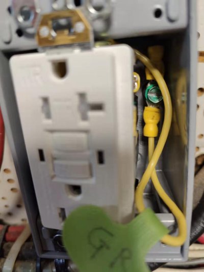
Image_20240318085050.jpg

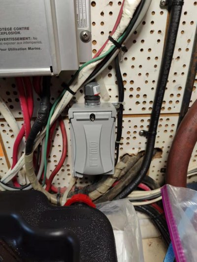
The good result is the final product is working. Thanks a lot for your help!

Image_20240318085045.jpg
 
I noticed the outlet has lost power. In my test, It turned on and off in a wiggle. The terminals are still tight. Only thing I noticed is the insulation on the neutral has broken, exposing strands. So I applied heat shrink tubing on the wires. Now the ground wire connector has become too thick to go inside the elec box. I'm thinking to cut it away and make a coil around the grounding screw. Is there any risk I should not neglect?
IMG20240422000927.jpg
 
The grounding conductor (normally the insulation is green) could be simply a bare wire without any insulation and likely is so in your house's wiring. As such, replace the grounding conductor's insulated locking fork terminal with an uninsulated version, no heat shrink is required. Don't twist stranded conductors around terminal screws and try to clamp.

Of more concern is the fact that there is a defect in the circuit somewhere, evidenced by your "It turned on and off in a wiggle" statement. To find this defect, you may be tempted to work on the circuit when it is live.
Don't do that, there are other safe ways to perform this work. A mistake on a live circuit can be fatal!
i checked the terminations didn't see other defects. unless the inside wire stands snapped when I wind them inside the electrical box.
 
Greetings,
Ms. p. I notice your 110v ground is a yellow wire. Not sure BUT I think yellow is solely for 12v systems so as to not get them confused with 110v systems which, I'm pretty sure should be green. Also your 110v and 12v systems should NOT be connected in ANY way, even the grounds. I await another member to correct me IF I'm remembering incorrectly.
no, I didn't connect the 12v dc to 110 v system. don't see any reason for doing that.
I was looking for a 12g stranded wire in hd and the store cut the yellow wire as a gift. the same green wire was not available. so I used it as the grounding with a label attached.
 
Is solid core wire inferior to stranded wire ?
for regulatory requirement refer to this post: solid - type 1 is not in compliance

1713801473591.png
 
Back
Top Bottom