Barking Sands
Guru
- Joined
- Dec 24, 2019
- Messages
- 889
- Location
- United States
- Vessel Name
- M/V Intrigue
- Vessel Make
- 1985 Tung Hwa Senator
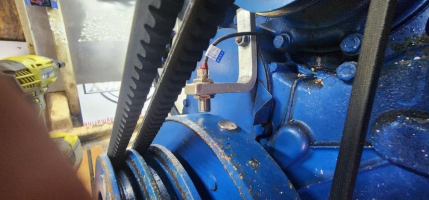
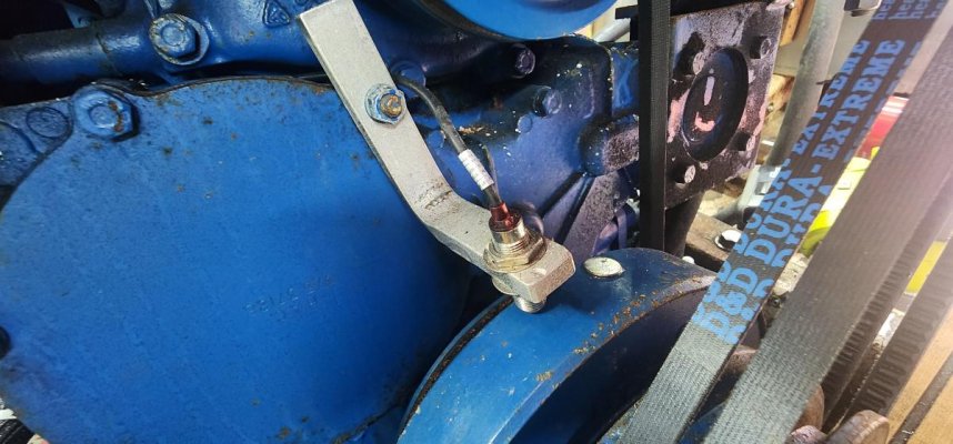
I just got done figuring out a solid way to drive your old original alternator driven W signal tachometers from a hall effect sensor/magnet mounted to the front of the motor and signal adapter for around $110. Alternator driven tach signals are not the best and can be finicky. But many times people want to retain the original tachometer but use a different signal that might be more accurate and less finicky. I went through several variations before I settled on this one and I hope it will be reliable and accurate. Really you can use these two items to drive any tachometer. Its just been that W signal tachs have been harder to adapt. I made a video outlining all the details on how too and what items. Hopefully its useful to someone. I know I looked and looked and there was no clear roadmap if you wanted to retain your W signal tachs but use a better signal.