Hello TF,
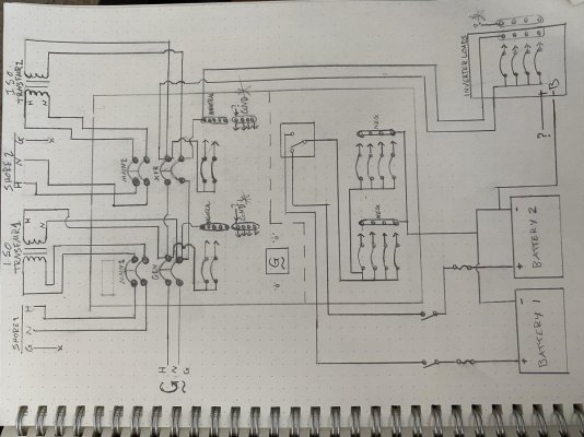
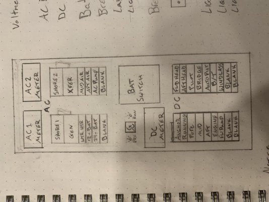
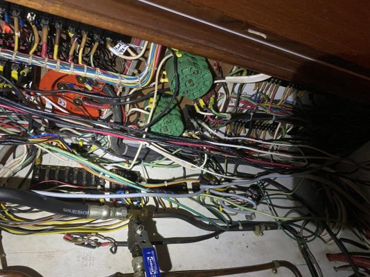
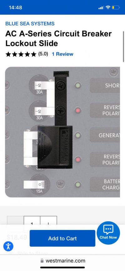
I’m in the works of rewiring my boat and installing a new panel I’m making to fit my needs, I have 2 30amp shore power lines, an 8.5kW generator, and a 2500w inverter. I’m ditching the “Ship-Shore” transfer switches and replacing them with double pole breakers with “lock out slides” to allow only 1 AC source to supply the loads. I will be using an inverter sub panel to prevent back-feeding the inverter as well
I’ve done an incredible amount of research online and in forums, but what I’m having issues with is my AC neutral to ground connections and there seems to be no clear answers online.
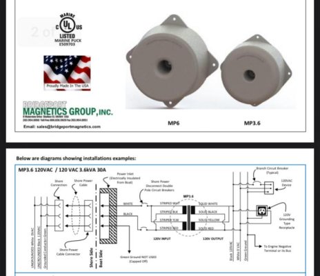
I understand the neutral and ground need to be connected at the source (gen and inverter do this automatically). But for my isolation transformer, there is no ground connection available on the secondary winding side. So how/where do I connect my neutral and ground?
See below images
I’m in the works of rewiring my boat and installing a new panel I’m making to fit my needs, I have 2 30amp shore power lines, an 8.5kW generator, and a 2500w inverter. I’m ditching the “Ship-Shore” transfer switches and replacing them with double pole breakers with “lock out slides” to allow only 1 AC source to supply the loads. I will be using an inverter sub panel to prevent back-feeding the inverter as well
I’ve done an incredible amount of research online and in forums, but what I’m having issues with is my AC neutral to ground connections and there seems to be no clear answers online.
I understand the neutral and ground need to be connected at the source (gen and inverter do this automatically). But for my isolation transformer, there is no ground connection available on the secondary winding side. So how/where do I connect my neutral and ground?
See below images
Attachments
Last edited: