Isolation Transformer Wiring

The friendliest place on the web for anyone who enjoys boating.
If you have answers, please help by responding to the unanswered posts.

markpj23

Senior Member
Joined
Mar 25, 2021
Messages
199
Vessel Name
Black Horse
Vessel Make
Med Yachts 62
While poking around the boat today I found part of the electrical connection access cover on the isolation transformer was not installed. No biggie, I'll just put it back on... hmm that looks interesting.....


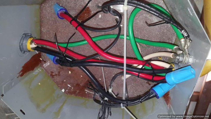
The shore power input side to the transformer has its negative and external ground leads tied to the same terminal on the frame. The shipboard side wiring is just L1, L2 and external ground. The neutral lead is not connected. The external ground is bridged across the transformer and is common to both input & output sides, from what I can see in the picture. (Input lead is on the right side of the picture)


I seem to recall that this setup can cause issues in marinas with the new GFCI sensing pedestals? The system obviously works but is it the way it should be?
 

Attachments

  • IsoTransfrmr.jpg
    IsoTransfrmr.jpg
    125.8 KB · Views: 57
I'm going to guess that you have 120/240V split phase on your boat, and that you use a 120/240V 50A shore connection?


I think you have the input and output cables mixed up. At least it would make a lot more sense if the cable on the left were the input and the right were the output.


Starting at the left which I think is the input, It's only using red and black which would be L1 and L2. Neutral (white) isn't used, and that's correct. The green ground is tied to the output ground and the output neutral which is not right. In fact it pretty much completely defeats the purpose of the isolation transformer. If you have a marine isolation transformer, it will have a wire that disappears into the interior of the transformer that is a protective shield. That's what the shore-side ground is supposed to be connected too. But if such a connection exists, I'm not seeing it.


Otherwise it appears to be wired correctly, but a schematic of the transformer would help confirm everything. Usually there is a sticker or placard somewhere on the transformer that shows how it should be wired up. Any chance you could post a clear picture of it? That would show whether there is a shield connection.
 
I'm going to guess that you have 120/240V split phase on your boat, and that you use a 120/240V 50A shore connection?
Yes that's right.


I think you have the input and output cables mixed up. At least it would make a lot more sense if the cable on the left were the input and the right were the output.
Yes my mistake, you are correct the input is on the left.

...a schematic of the transformer would help confirm everything...
Let me see what I can find. If there is one, of course it's not easily visible inside the locker.
 
Let me see what I can find. If there is one, of course it's not easily visible inside the locker.


Never. It will be on the back side, up against a bulkhead. :ermm: You might try taking a few blind pictures just to see if there is anything worth checking more closely.
 
From reading your description, I believe your transformer is wired incorrectly.

I wouldn't just blindly "hook something up".

You have two choices depending on your knowledge of electricity:

1) Find the installation diagram from the manufacturer (of the transformer) and make sure every wire is connected (or not connected) according to the diagram.

2) Hire a qualified marine electrician to inspect and if necessary, rewire your transformer properly.

Incorrect wiring of the transformer can either negate its function in isolating your boat from the marina's electrical system or create a vary dangerous situation on your boat.
 
Nigel Calders book Boatowners Mechanical and Electrical Manual has isolation transformer wiring options illustrated if you don't have a diagram for your transformer.
 
Nigel Calders book Boatowners Mechanical and Electrical Manual has isolation transformer wiring options illustrated if you don't have a diagram for your transformer.


Thanks - I have that book aboard and will look it up.
 
The wiring diagram is usually inside the cover that is removed. What is the model number and manufacturer of the xfmr. It looks like a ubiquitous Acme.

Also, each of the leads coming out of the block of epoxy/sand (yup, that's what they use) has a label on it; e.g., H1, H2, X1, X2 or the flying lead has the designation printed on the insulation. Find these IDs and map out how it is wired using Nigel's book as a guide.

In general, for 240VAC split phase, only 240VAC, i.e., L1, L2, and G come aboard from shore-there is no N just as in your photo. G is connected to the shield between primary and secondary-not to the case. On the secondary side, split phase is created by bonding N and G and then tapping off L1>N for one leg of 120VAC; L2>N for the second leg of 120VAC and L1-L2 for 240VAC.
 
A dead giveaway that the wiring was by an armature is the use of wire nuts.
 
OP: Looking at the photo-both the shore and boat safety grounds (green wires) are bonded to the boat side neutral. Either the xfmr was mis-wired or it was wired as a polarization xfmr. See Calder.
 
Back
Top Bottom