BDofMSP
Guru
- Joined
- Sep 5, 2013
- Messages
- 905
- Location
- USA
- Vessel Name
- Gopher Broke
- Vessel Make
- Silverton 410 Sport Bridge
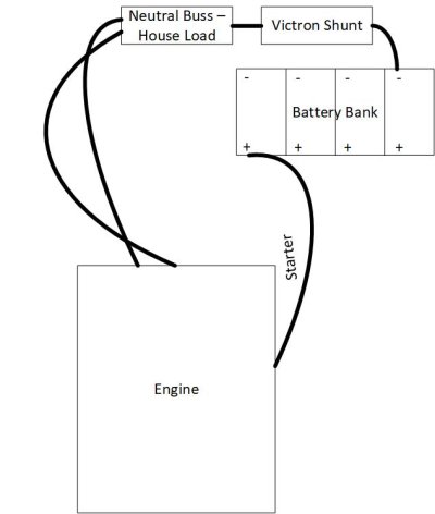
I had an idea as I was staring at my problem of not having the neutral long enough to reach the farthest battery. I have also been desiring a battery monitoring solution for these banks. Researching the Victron BMV 712, it seems that I connect the neutral of the battery bank to the Shunt, and then from the Shunt to the house load. Maybe that solves my problem?
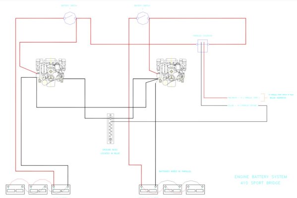
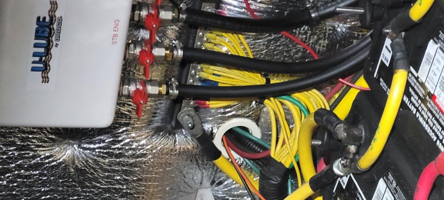
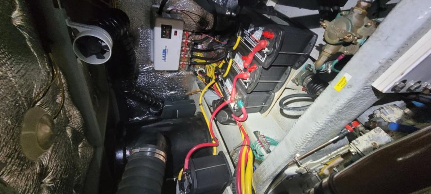
Today the battery negative post is connected directly to the engine. However, the house load is connected to a buss bar (right above the batteries) which is ALSO connected to the engine. A diagram and a photo are attached. Remember, my bank serves both house and starting.
My question is two parts:
a) could I install the Victron by simply making a new cable from the battery bank negative cable and the Shunt, and then connect the shunt to the neutral buss bar (for house load)
b) and if so, then what do I do with the cable that currently runs from the battery to the engine? Connect it to the load side of the shunt too? Or connect it to the neutral buss?
A diagram for that is also attached.
Thanks!
BD