Alternator grounding

The friendliest place on the web for anyone who enjoys boating.
If you have answers, please help by responding to the unanswered posts.

helm

Senior Member
Joined
Apr 24, 2015
Messages
141
Location
USA
Vessel Name
Maverick
Vessel Make
Lindell 36
Trouble shooting a no output alternator on our starboard engine today. Found the Ring terminal for the alternator ground while intact was corroded through and came apart as soon as I touched it. Replaced the terminal and voila alternator output. The question is this. The alternator ground wire is attached to the engine block, would there be an advantage to running the Alternator ground wire to a battery negative terminal and avoid having additional current running through the engine and its components or just leave as is grounded to the engine block.
Thanks
Eric
 
Depends on amperage among other things. My primary alternator (65 amps) is factory wired negative through the block. The second alternator (220 amps) that charges the house bank, has its own negative (4/0 same as positive) wired to the distribution buss. With a multi stage regulator, the alternator can be outputting at 220 amps for over an hour. I like the conductors to be oversized in that situation. You can have impressive failures with lots of amps!

Ted

Yup!
 
"I like the conductors to be oversized in that situation"

With in reason oversized is better than barely enough.

With an older boat there will be loads of wiring to help, far easier to get a good crimper and good terminal ends and 500 or 1,000 ft of # 10 and go to it.
 
Ted, when you say distribution bus, I assume you mean the ground bus. Just checking because I am about to rewire the positive output from my alternators directly to my two battery banks. Presently, they go through the starter feed. I am not at the boat right now and I cannot remember how they are grounded but it is likely through the engine block. If so, would it be better to ground the alternators directly to my ground bus?
Depends on amperage among other things. My primary alternator (65 amps) is factory wired negative through the block. The second alternator (220 amps) that charges the house bank, has its own negative (4/0 same as positive) wired to the distribution buss. With a multi stage regulator, the alternator can be outputting at 220 amps for over an hour. I like the conductors to be oversized in that situation. You can have impressive failures with lots of amps!

Ted
 
Ted, when you say distribution bus, I assume you mean the ground bus. Just checking because I am about to rewire the positive output from my alternators directly to my two battery banks. Presently, they go through the starter feed. I am not at the boat right now and I cannot remember how they are grounded but it is likely through the engine block. If so, would it be better to ground the alternators directly to my ground bus?

That's the way mine is done. Nothing is connected directly to the batteries except the actual feed wire that then runs to a buss bar/ distribution buss.
That goes for both the positive and negative leads. Nothing is connected directly to the batteries except that one pair of leads per battery.

My alternator is then connected directly to those busses, both pos. and neg.
The alternator case and brackets are of course grounded that way also which give the engine its ground for the small loads such as sensors, guages.

Just as a note if the question comes up my engine uses an isolated ground, not the common ground through the block, so it too has a dedicated ground to its battery set.
 
Thanks for the help you guys
I will have to rethink our alternator wiring. Each alternator is currently wired positive to the starters and ground to the engine blocks. I hadn’t really delved into the wiring on our Lindell as everything was working until the issue with starboard alternator.
Thanks again
Eric
 
Be sure to Fuse the positive lead to the battery. It is recommended that the fuse be 140% of the Alternator Amperage. Put this fuse in line between the Alt and the House bank.
Taras
 
ted, when you say distribution bus, i assume you mean the ground bus. Just checking because i am about to rewire the positive output from my alternators directly to my two battery banks. Presently, they go through the starter feed. I am not at the boat right now and i cannot remember how they are grounded but it is likely through the engine block. If so, would it be better to ground the alternators directly to my ground bus?

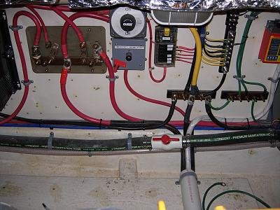
I apologize that I don't have a better picture available at the moment. The below one is during the refit, is incomplete, and lacks the lexan cover on the positive buss.

It's important to be clear on this point. On DC circuits, there is a positive, a negative, and a boat bonding system (sometimes referred to as a ground). THIS BONDING SYSTEM IS NOT THE GROUND FOR ANY OF THE 120 VAC SYSTEM (shore power or generator).

In the picture the positive buss is to the left, negative in the center, and boat bonding system to the right.

The positive distribution buss has the battery bank with disconnect switch above, second alternator under the same bolt as the battery bank, and then fused leads to the main breaker panel, windlass, dinghy crane, and inverter / battery charger.

The negative buss has the battery bank cable (yellow) coming from the top, second alternator under the same bolt as the battery bank, and then leads to the main breaker panel, windlass, dinghy crane, inverter, and 3 other negative busses.

The bonding system hasn't been finished in this picture, but you can clearly see a cable between the negative buss and the bonding buss.

To your question:
Depending on where the negative wire from the battery bank is attached to the engine, you can have several pieces of metal bolted together that form the electrical path between the alternator and the negative battery cable. Certainly not optimal for a low amperage alternator (but acceptable). This adds a fair amount of resistance and possibly poor multiple connections for a high output alternator in full output tied to a house battery bank. IMO, running tinned multi strand copper cable from the battery negative buss to the alternator frame seems like a no brainer. BTW, there is also a negative cable to the engine starter flange.

DSCN1065.jpg

Ted
 
Thanks Ted. Now, it's clear to me. Bottom line is the recommendation is "home runs" for both positive and negative leads from the alternators to their respective bus bars.
I apologize that I don't have a better picture available at the moment. The below one is during the refit, is incomplete, and lacks the lexan cover on the positive buss.

It's important to be clear on this point. On DC circuits, there is a positive, a negative, and a boat bonding system (sometimes referred to as a ground). THIS BONDING SYSTEM IS NOT THE GROUND FOR ANY OF THE 120 VAC SYSTEM (shore power or generator).

In the picture the positive buss is to the left, negative in the center, and boat bonding system to the right.

The positive distribution buss has the battery bank with disconnect switch above, second alternator under the same bolt as the battery bank, and then fused leads to the main breaker panel, windlass, dinghy crane, and inverter / battery charger.

The negative buss has the battery bank cable (yellow) coming from the top, second alternator under the same bolt as the battery bank, and then leads to the main breaker panel, windlass, dinghy crane, inverter, and 3 other negative busses.

The bonding system hasn't been finished in this picture, but you can clearly see a cable between the negative buss and the bonding buss.

To your question:
Depending on where the negative wire from the battery bank is attached to the engine, you can have several pieces of metal bolted together that form the electrical path between the alternator and the negative battery cable. Certainly not optimal for a low amperage alternator (but acceptable). This adds a fair amount of resistance and possibly poor multiple connections for a high output alternator in full output tied to a house battery bank. IMO, running tinned multi strand copper cable from the battery negative buss to the alternator frame seems like a no brainer. BTW, there is also a negative cable to the engine starter flange.

View attachment 105099

Ted

Too bad you don’t do nice work... Looks great!
 
I am in a "cold starting" area that tests starting/charging circuits annually.
Running your negative battery cable directly to a starter bolt and running an alternator ground to the same point are both very good ideas. Ideally the alternator ground should be the same size as the + output wire.
 
Back
Top Bottom