Wiring a 49 year old 34’ MT

The friendliest place on the web for anyone who enjoys boating.
If you have answers, please help by responding to the unanswered posts.

J. Landin

Veteran Member
Joined
Dec 26, 2023
Messages
33
Vessel Name
Lehman’s Terms
Vessel Make
1975 34’ Marine Trader Sedan
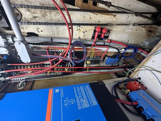
As promised I am working on the mess of wiring on my boat and am trying to get pictures as I go to document it.

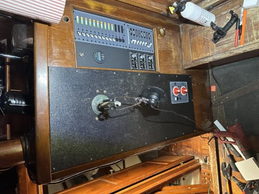
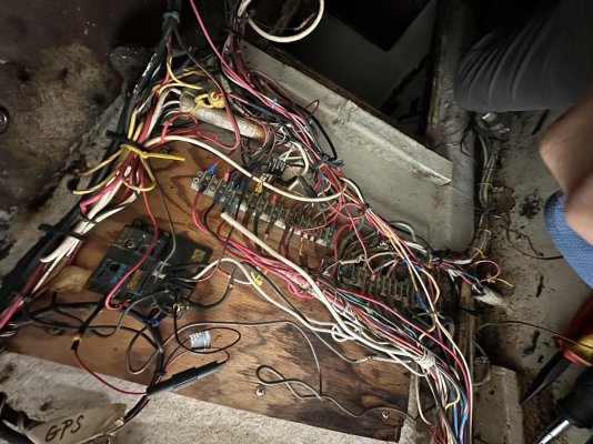
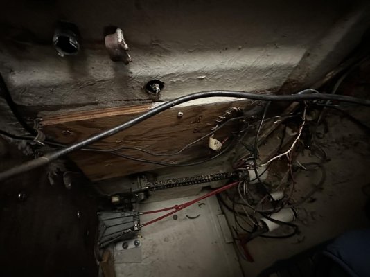
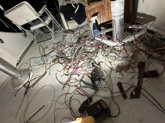
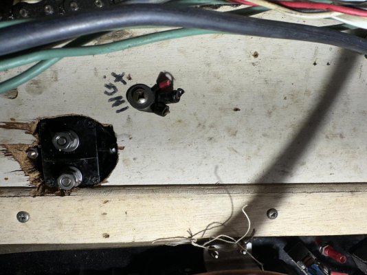
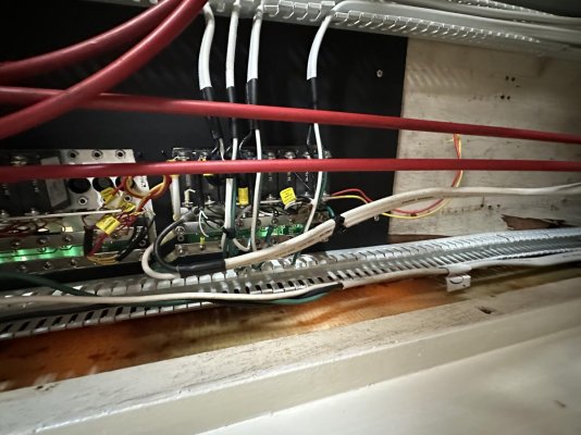
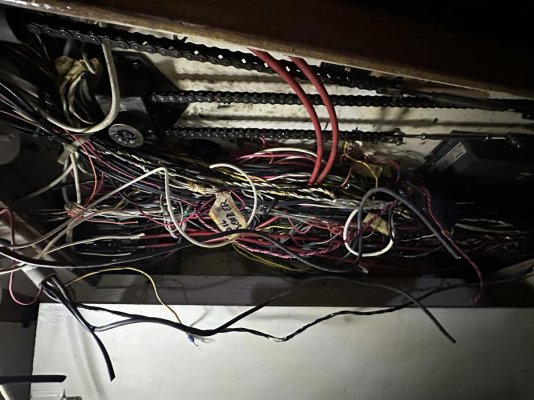
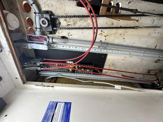
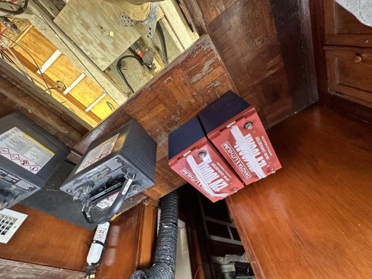
I started by climbing into the fly bridge to access the situation up the. Attached are the before, after and pile of wires removed. It is hard to imagine what went through the POwners mind when running things the way they did.

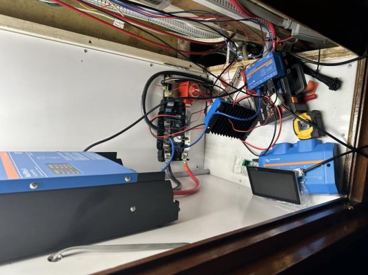
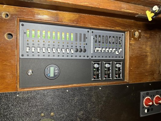
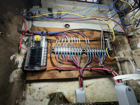
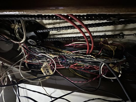
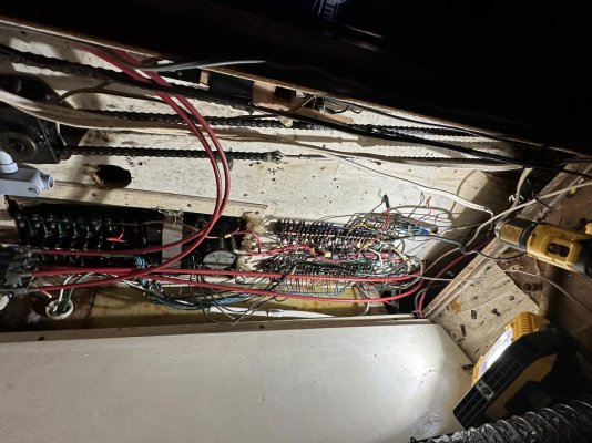
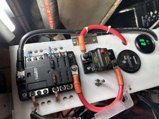
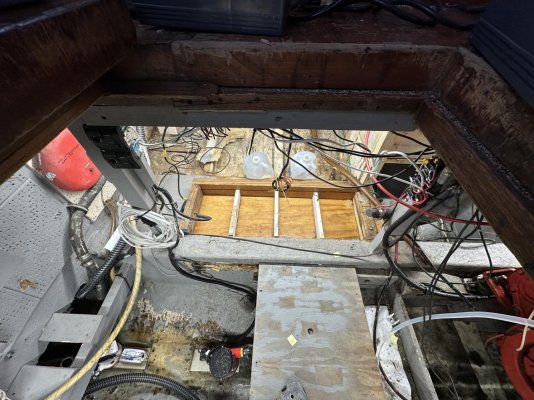
Since I can’t trust that any of the wires or terminations are reliable it all has to go. I cut everything out of the fly bridge and pulled the wires through the wood steering tube into the main cabin. From there I traced down the upper wire termination points and cut them at their terminal strip or origin.

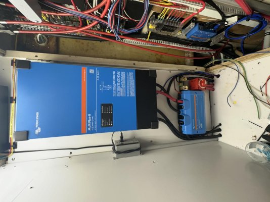
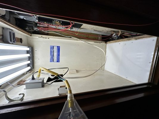
It was amazing to see 18awg 110v A/C secured to a terminal strip that has 80 % 12 v dc circuits on it. This 18 awful wire was powering the bilge 110v power for the battery charger. Conductor way undersized.
 

Attachments

  • IMG_0699.jpg
    IMG_0699.jpg
    189.6 KB · Views: 36
Once I cleared all the fly bridge wiring from the lower helm I went below into the engine/bilge room to pull these wires through from below. Probably half the wires had been abandoned over the years.
 

Attachments

  • IMG_0700.jpg
    IMG_0700.jpg
    93.8 KB · Views: 16
  • IMG_0701.jpg
    IMG_0701.jpg
    195 KB · Views: 20
Pictures behind the lower helm station.
 

Attachments

  • IMG_0696.jpg
    IMG_0696.jpg
    140.2 KB · Views: 13
  • IMG_0697.jpg
    IMG_0697.jpg
    144.3 KB · Views: 10
  • IMG_0709.jpg
    IMG_0709.jpg
    171.9 KB · Views: 14
  • IMG_0707.jpg
    IMG_0707.jpg
    149.9 KB · Views: 16
Last edited:
It can be amazing what POs do to electrical wiring. On our last boat I found a pair of #6 wires run up to the flybridge and just hanging loose. So I started tracing them back. They went directly to the house bank and connected to the batteries without any overcurrent protection at all. I pulled hundreds of feet of abandoned wires out. Actually got enough room to run some new wires up to the flybridge…
 
Sorry for the dark pictures. I found it interesting that the PO used a wood screw, screwed in the back of the panel to tie together the the “ignition” from the upper and lower helm.

I filled three 5 gallon buckets with wire so far (approx 100 lbs)
 
Sorry for the dark pictures. I found it interesting that the PO used a wood screw, screwed in the back of the panel to tie together the the “ignition” from the upper and lower helm.

I filled three 5 gallon buckets with wire so far (approx 100 lbs)

i pulled a couple of dock carts worth from my boat when we re-wired. PO had service loops around 15 feet long in some places. just big coils of wire stacked up. i recovered enough almost new 4/0 wire to re-make all my battery leads and then some. amazing.
satisfying job when complete though, nice to have an item turn on every time you hit the switch.
 
God help you!! Looking at it, I "think" I would rip everything out and start from scratch.

I have a few dead wires on my boat. I ripped out what I could and some I left because they were intertwined with the live wires in bundles and raceways.
 
It's not always PO's that rewired the boat crazy, sure a lot....but a lot of boats from the 80s and earlier had quite the rats nest straight from the factory with plenty of undersized and no fused/CB protected wires too.
 
Yep normal PO wiring horrors. There’s no limit to the varieties. It would be fun to start a new thread for the creative methods of wiring found on boats.
 
It's not always PO's that rewired the boat crazy, sure a lot....but a lot of boats from the 80s and earlier had quite the rats nest straight from the factory with plenty of undersized and no fused/CB protected wires too.

That's my 1973 Concorde 41. Everything works but the wiring is a mess. They used the same wire for AC and DC so all the DC positive wires are black and the DC negatives are white. I would have done that the other way around so at least one of the colors was correct. AC is all the right colors. And household type breakers on both AC and DC. I didn't even know you could do that but I shorted a DC circuit once and the breaker tripped so I guess AC breakers do work on DC. There are 16 DC breakers but only 4 negative wires on the neg buss in the panel. The other 12 must be grounded to the engines, I haven't found where. Crazy.
 
Last edited:
I just pulled a bunch of excess wiring from our boat last week.

You have a wood chase for your steering chain and wiring to go to the flybridge? I've been considering getting rid of the stainless post we have that has our steering chain and wires going through it from lower to upper helm. I am not a fan of the wiring running right in there with the chain. I may make a wood one and separate the chain and wiring. Also by having the wood post it would make an easier mounting point for things.

I always enjoy seeing other people's posts about their work and findings on their older trawlers.
 
I am running 2 separate 1/2” pvc conduit into the wood tube. It is a tight fit but certainly adds more protection to the wires and chain (the wood tube surrounds a fiberglass tube…the chains run in separate plastic tubes inside)

I am planning out my circuits now and I think I can get away with 8 dc switch/breakers at the helm and move the fresh water pump, wash down and bait well pump over to a switch panel at the sink.

Anchor light
Running lights
Salon lights
Forward cabin lights
Spreader lights
Electronics vhf
Electronics gps/sounder

What do you all think? Any suggestions?
 
Wiring

Last boat I rewired was simpler than yours. But I bought a boat wiring harness off eBay long enough. Gave me 20 wires color coded different in a harness to work with
 
I am planning out my circuits now and I think I can get away with 8 dc switch/breakers at the helm and move the fresh water pump, wash down and bait well pump over to a switch panel at the sink.

Anchor light
Running lights
Salon lights
Forward cabin lights
Spreader lights
Electronics vhf
Electronics gps/sounder

What do you all think? Any suggestions?

Yes, include a couple of spare circuits (and a pull rope) for the future.
 
It's not always PO's that rewired the boat crazy, sure a lot....but a lot of boats from the 80s and earlier had quite the rats nest straight from the factory with plenty of undersized and no fused/CB protected wires too.

I visited a Boston Whaler dealership in Melbourne FL with my wife, jumped onboard the 25 foot-ish fishing boat that cost 1/3 million bucks, and asked the tech to open the battery storage area. Big house bank installed by the dealer. It was the most horrendous, random assortment of wires installed by a bunch of teenagers. I couldn't believe the dealership could respect itself, trying to get away with that type of craftsmanship. Felt really bad for whomever the unknowing buyer was, who obviously was not very astute in the marine world but was trusting their dealer to give them a proper vessel.
 
As Mako says it is not only P.O.s that make wiring messes. I've seen enough so called professional messes.
 
If I were re-wiring after a complete rip out and if the boat's layout made the approach reasonable I consider sub panels located near the areas they serve.
I am running 2 separate 1/2” pvc conduit into the wood tube. It is a tight fit but certainly adds more protection to the wires and chain (the wood tube surrounds a fiberglass tube…the chains run in separate plastic tubes inside)

I am planning out my circuits now and I think I can get away with 8 dc switch/breakers at the helm and move the fresh water pump, wash down and bait well pump over to a switch panel at the sink.

Anchor light
Running lights
Salon lights
Forward cabin lights
Spreader lights
Electronics vhf
Electronics gps/sounder

What do you all think? Any suggestions?
 
If I were re-wiring after a complete rip out and if the boat's layout made the approach reasonable I consider sub panels located near the areas they serve.

I agree. I have already done a few subpanels. One in the rear of the boat for various accessories. One in the overhead where all the Garmin type electronics run and one that goes to the flybridge. Each on its own main breaker with appropriate sized wire (pos and neg) to handle whatever expected loads I might use in those areas plus room for expansion. At each location I just use a Blue Seas fuse panel with negative bus. Makes adding future devices a snap.
 
I agree. I have already done a few subpanels. One in the rear of the boat for various accessories. One in the overhead where all the Garmin type electronics run and one that goes to the flybridge. Each on its own main breaker with appropriate sized wire (pos and neg) to handle whatever expected loads I might use in those areas plus room for expansion. At each location I just use a Blue Seas fuse panel with negative bus. Makes adding future devices a snap.

I am interested in running a sub panel to my flybridge and another to run my alarm panel, charging ports and vhf in an overhead console (to be built) at the lower helm. Probably a spring project when I figure out how to start.
 
Update:

Sorry it’s been so long since I posted. I currently have 4ea 5 gallon buckets full of wire stripped from the boat. I removed the old ac/dc panel and hooked up a simple shore power circuit to get me by until I finish the new AC panel.

I installed 3 sets of oil pressure and water temperature sensors on the engine. Each set has its own dedicated harness which enters a starboard junction box below which houses the “Engine” fuses and circuits and a set of gauges for monitoring while below. All wires terminate at a terminal strip in the junction box and then continue to the salon helm and fly bridge via gray PVC conduit. Trying to keep this wiring refit simple and neat. IMG_0748.jpg

IMG_0750.jpg

IMG_0751.jpg

IMG_0752.jpg

IMG_0753.jpg
 
More
 

Attachments

  • IMG_0723.jpg
    IMG_0723.jpg
    202.4 KB · Views: 111
  • image.jpg
    image.jpg
    124.2 KB · Views: 14
It’s been a pretty productive couple of weeks. I finished running all the cable tray track for AC and DC loads behind the helm and down below decks. All new AC cables from main helm panel to outlets. This includes new outlets, boxes if needed and SS covers. Shore power is just temporarily installed into the AC panel until I get my new inverter in.
 

Attachments

  • IMG_0756.jpg
    IMG_0756.jpg
    122.5 KB · Views: 11
  • IMG_0758.jpg
    IMG_0758.jpg
    190.8 KB · Views: 9
  • IMG_0762.jpg
    IMG_0762.jpg
    128.7 KB · Views: 8
Before and after:
 

Attachments

  • IMG_0696.jpg
    IMG_0696.jpg
    140.2 KB · Views: 7
  • IMG_0758.jpg
    IMG_0758.jpg
    190.8 KB · Views: 9
Ordered all and received most of my Victron equipment. Multiplus II 3000, Cerbo GX w/7” screen, 30A B to B charger and a Smart Shunt. Pulled the 6v lead acid golf cart batteries for the house and replaced them with 4 Dakota Lithium 100Ah batteries (more to come).
 

Attachments

  • IMG_0759.jpg
    IMG_0759.jpg
    195.3 KB · Views: 7
  • IMG_0760.jpg
    IMG_0760.jpg
    189.7 KB · Views: 5
  • IMG_0761.jpg
    IMG_0761.jpg
    196.3 KB · Views: 7
My Victron Multiplus II came in yesterday and the box was in pretty rough shape from “shipping”. I informed Amazon. They are picking this one up today and express sending out the replacement.

Well…it gets worse! I cut open the box to get it squared back up and re-tape and to my surprise found a Renergy Inverter/Charger in the Victron box. Someone was trying to pull a fast one (well I guess they actually did). I let Amazon know about the situation just so I wouldn’t be the one blamed for the swap.
 

Attachments

  • IMG_0768.jpg
    IMG_0768.jpg
    174.4 KB · Views: 6
  • IMG_0776.jpg
    IMG_0776.jpg
    128.2 KB · Views: 8
  • IMG_0775.jpg
    IMG_0775.jpg
    142.9 KB · Views: 6
Been a while since I updated this thread. Been a bit busy.
 

Attachments

  • IMG_0808.jpg
    IMG_0808.jpg
    134.9 KB · Views: 10
  • IMG_0810.jpg
    IMG_0810.jpg
    195.9 KB · Views: 7
  • IMG_0811.jpg
    IMG_0811.jpg
    197.4 KB · Views: 7
  • IMG_0820.jpg
    IMG_0820.jpg
    129.4 KB · Views: 9
  • IMG_0821.jpg
    IMG_0821.jpg
    197 KB · Views: 7
  • IMG_0833.jpg
    IMG_0833.jpg
    196.8 KB · Views: 7
  • IMG_0825.jpg
    IMG_0825.jpg
    197.7 KB · Views: 13
Back
Top Bottom