What is this connector? (see attachment)

The friendliest place on the web for anyone who enjoys boating.
If you have answers, please help by responding to the unanswered posts.

TTT

Member
Joined
Nov 8, 2021
Messages
5
Vessel Name
Ruffles
Vessel Make
Camano 31, Hull # 206
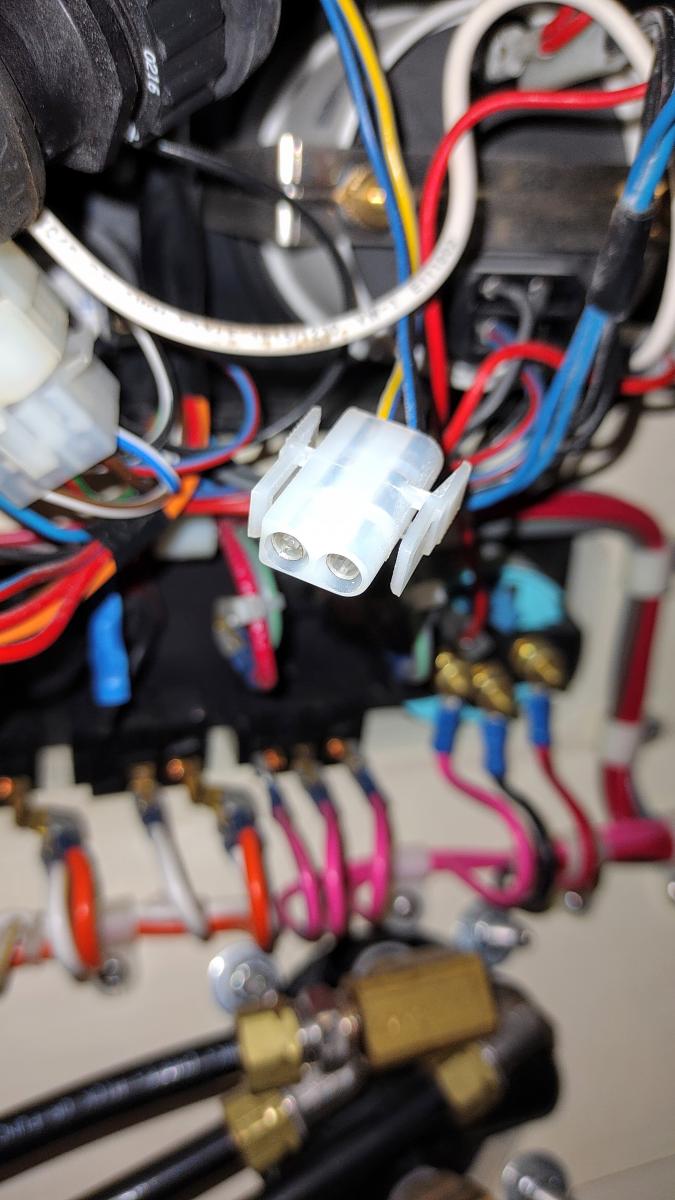
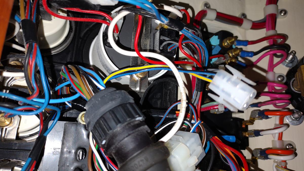
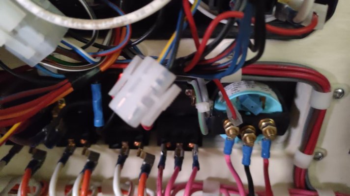
Its behind the tach in the dashboard. My guess is that is a EDC (electronic diesel control) J1708, J1587 or J1939 connector to monitor the engine.

The reason I ask is I would like to hook up a Yacht Devices Engine Gateway to and monitor the engine via wifi.
https://www.yachtd.com/products/engine_gateway.html

Has anyone out there hooked up a Yacht Devices Engine Gateway to their Camano?

Thanks in advance!
 

Attachments

  • IMG_20211107_142709049.jpg
    IMG_20211107_142709049.jpg
    77.9 KB · Views: 43
I should probably mention its the white two wire connector in the middle of the photo. :)
 
Do a google search for Molex connector.
 
Welcome aboard.
What engine and year?
Can you show a pic of the pin arrangement?
 
It really could be almost anything. I’d try to find a schematic for the boat, or more likely the engine system.
 
  • Like
Reactions: TTT
I doubt that it is any kind of J1939 connector, as that requires shielding, I believe.
 
  • Like
Reactions: TTT
Much better pictures

29919-albums1174-picture7193.jpg

29919-albums1174-picture7192.jpg
 
Extra Wire

Not sure if this helps. This is from the Volvo Electronics manual
 

Attachments

  • Extracted pages from Workshop Manual_Electrical Systems_Wiring Diagrams_Page1.jpg
    Extracted pages from Workshop Manual_Electrical Systems_Wiring Diagrams_Page1.jpg
    58.2 KB · Views: 20
  • Extracted pages from Workshop Manual_Electrical Systems_Wiring Diagrams_Page2.jpg
    Extracted pages from Workshop Manual_Electrical Systems_Wiring Diagrams_Page2.jpg
    86.2 KB · Views: 25
Thanks! I don't see blue-black or blue-yellow on the diagram though. I will have to run down to the boat with these diagrams and double check each wire. If nothing else this will be a handy reference if I need to change out any controls or guages. :)
 
I gave you the wrong page

TTT,
Look at this page. I pulled the wrong one last time.
It shows a Blue/Black & Blue Yellow = #18 which is the connector for Turbo/Reverse Gear
 

Attachments

  • Workshop Manual_Electrical Systems_Wiring Diagrams p35.pdf
    52.6 KB · Views: 24
The Gauge

This looks like the gauge that would connect.
I was curious to see & I have the same connector on my lower station panel.
Seems it runs to the control box on the engine, assume from there you would have to place the sensors to the gear & turbo?
 

Attachments

  • 0d1aa2276a5a991a161a684ce4eb0e0b.jpg
    0d1aa2276a5a991a161a684ce4eb0e0b.jpg
    31.5 KB · Views: 16
  • 815c920c5dd05db36af10e339200fbc8.jpg
    815c920c5dd05db36af10e339200fbc8.jpg
    45.2 KB · Views: 19
Last edited:
  • Like
Reactions: TTT
I think you just solved it he mystery! Thanks! So it's a boost gauge and whatever the gauge with the gear on it is (reverse? Reverse what?).
That makes sense since I don't have a boost gauge. Now if only I could find the J1708 connection!
 

Latest posts

Back
Top Bottom