Troubleshooting gauges

The friendliest place on the web for anyone who enjoys boating.
If you have answers, please help by responding to the unanswered posts.

GrandWood

Senior Member
Joined
Jul 16, 2022
Messages
171
Hello all, trying to get my gauges to read right. So I’m starting at the key switch, as that’s where the 12v to the gauges is comming from. With key off, I have 12v at the key switch comming from engine room, and zero volts at the gauges, which seems right to me. When I turn the key on, the voltage at the key switch fluctuates, jumping all over.

On the pos terminals of the gauges it’s the same inconsistent voltage read at key switch, which it should be, straight wires.

Low oil pressure buzzer works, and its pwr is jumpered off the temp gauge. And that voltage is jumping all over just like at the key switch.

Port side gauges for oil temp and water temp jump up to 60 psi(oil) and 120f (temp) when key is turned on. Starboard side both remain at zero.

The voltage jumping around has me stumped, not sure if that’s right or what, seems it should be solid 12v.

The voltage at the starboard key switch jumps around as well.

Just wondering if the voltage fluctuation is right or wrong at the key switch when turned on.
 
Sounds like a bad key switch. You could just use a jumper and bypass it.
 
To answer your question you should get a stable 12 volt plus reading with key on. If you are using the same neg/ground test point for your key on and off test seems 99.9% sure it is the switch. But odd it is on both key switches. I suppose you could have some loose or corroded ground so you might check that side too.
 
So I been poking around, removing power from the flybridge gauges, just trying to see if some component/gauge is causing the voltage fluctuation, disconnecting individual gauges. Still have the voltage fluctuation. There is no ground on the key switches, they just move the 12v to gauges and start switch.

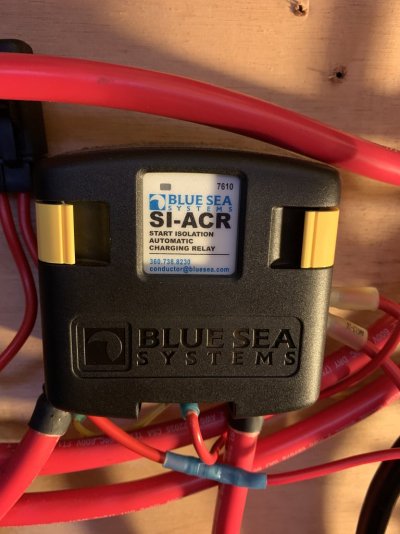
The power to the key switches comes out of this device pictured below. The 12v to the key switches comes out of the right side there in the middle. With key off it’s a steady 12v, switch key on and voltage varies like what I see on both key switches.

So it seems that something beyond the key switches is pulling the voltage down, which would be any one of the gauges, i don’t see anything else tied to the circuit.

Starter switches would be engaged turning the key further. And engine fires off no problem.


So I’m stumped why the low oil pressure buzzer, and both engines start, but the gauges are outta whack.

I grounded both the water pressure/oil pressure lines from the gauges and both read max at the lower helm and that is how they should act.

Flybridge gauges don’t move at all. I’ve disconnected the power from the flybridge gauges, and still lower helm gauges are not at zero when engine is not running, and voltage is still fluctuating.

So I’m stumped, could this device pictured be the problem, being something new to the boat? Anyone have any idea what it actually does?

I haven’t jumpered over the key switch in fear of blowing something up, especially this device.

Edit, the boat has been totally rewired, both ac/dc. There is no corrosion that I can see anywhere. Also the gauges are old Stuart Warner.
 

Attachments

  • IMG_1340.jpeg
    IMG_1340.jpeg
    128.8 KB · Views: 8
Read up on the device, it just isolates power from sensitive devices during start up
 
Send me a PM if you want and I can provide my cell #.

Correct, there should be no ground on the key switch. I am assuming you have a separate start button and the key switch is either on or off? That BluSea ACR is to isolate 2 battery banks. I think you should try to trace and draw out how your wiring connects from each battery all the way to the gauges. How many batteries and how are they configured? Twin engines each with a start bank and also another house bank?
I suspect that wire to your switch from the ACR is just there to sense when the starter is engaged and really should connect to the "on" side of your starter button and it forces the ACR to isolate the house bank from the start bank (so possible low voltages during heavy staring drain don't damage electronics) if so it likely is not where the gauges should get their power. If it would explain the voltage fluctuation as it is not supposed to see any 12v unless the starter is engaged. It would not impact the starting capability at all. Probably is impacting any engine charging of your non staring battery. I would spend some time reviewing the ACR installation guide and compare it to what you have.


From the ACR installation guide:

Minimum connections for operation:
• Connect one battery bank to stud terminal A.
• Connect the other battery bank to stud terminal B.
• Connect the quick connect terminal marked GND (ground) to the DC system ground through
a one amp in-line fuse to prevent fault currents from flowing in this wire.
1. Start Isolation (SI) Wire
• The 7610 ACR can be configured to automatically disconnect when the starting circuit is engaged.
Enable this feature to isolate the start circuit from the house circuits and prevent starting currents from
flowing through the ACR or starting current transients from interfering with loads on other batteries.
The reaction time of the 7610 ACR is fast enough to disconnect the battery banks before the
starting current rises in the starting circuit.
2. Remote indicator lamp – mirrors “COMBINED” LED on unit.
• Appropriate 12/24V LEDs include Blue Sea Systems PNs 8033 (amber), 8171 (red), or 8172 (green).
To connect a remote LED indicator:
• Connect the red wire of the LED to a 12/24V positive source through a one to two amp in-line fuse.
• Connect the yellow wire of the LED to the quick connect terminal marked LED.
Open/Close Cycling
• If your electrical system is configured with a charging source that cannot supply the full load current
being drawn from the receiving batteries, an open/close cycling process can occur. If this cycling
continues, the second battery bank could eventually discharge even though a charge source
is present.
Optional connections:
* Larger wire sizes may be
required to minimize voltage
drop in long wire runs.
For more information please
use the Circuit Wizard at
www.circuitwizard.bluesea.com.
To enable start isolation:
• Connect a wire from the quick connect terminal marked SI (starting isolation) to the
terminal or wire running from the start key switch to the starter solenoid. Make this
connection through an in-line fuse of one to ten amps. This connection can be made at the
start key switch or at the starter solenoid, but must be to the line that is positive only when
cranking. Connection to a line that is positive while the engine is normally running will
prevent the charging relay from working
 
Thank you Ken, I will go over the routing of the wires from the ACR, and the routing of the batteries. I have a 3 battery house bank, and one starting battery bank. Twin engines.
 
And I’m going to go over all the grounds on the gauges, remove and clean. And see where the ground comes from below. The rewire of the boat was done by previous owner, a supposed marine electrician did the work. It’s not a very neat install to my eyes, wires run here and there, nothing marked, and there’s old wires just diked off here and there.
 
I feel your pain. My 1976 Hatteras doesn't have a ton of mystery wires but I have found my fair share. Trying to think about the next owner as I make my own mods.
 

Latest posts

Back
Top Bottom