Blown Fuse

The friendliest place on the web for anyone who enjoys boating.
If you have answers, please help by responding to the unanswered posts.

Capt. Rodbone

Senior Member
Joined
Sep 6, 2020
Messages
172
Location
U.S.
Vessel Name
SV Stella Polaris MV Sea Turtle
Vessel Make
1978 VanDine Gaff rigged schooner, 1978 Grand Banks Classic Trawler
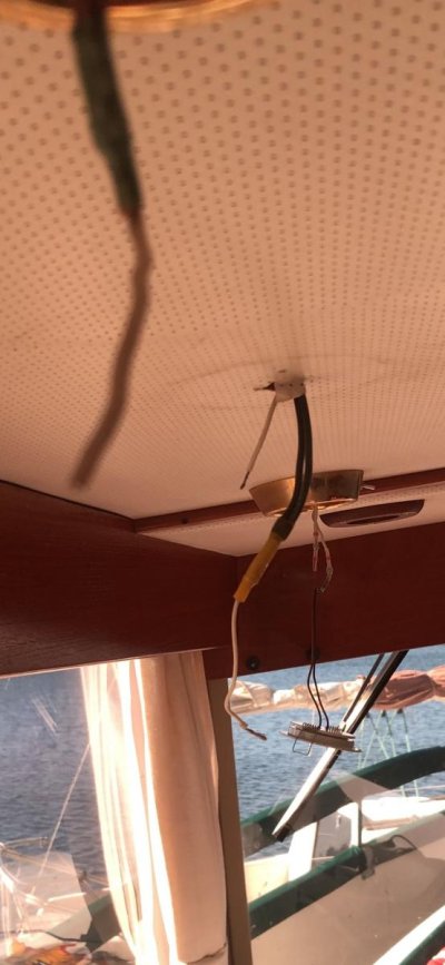
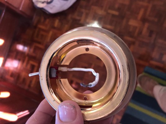
I have to admit my confidence is a bit shaken when my wife and I are planning to leave in a month on the GreatLoop and I can’t even figure out what should be in my opinion a pretty easy electrical problem. Electrical in general is my biggest weakness. I looked fairly hard for a school I could send myself to and even enrolled in a local junior college program about a year ago but quickly found out they zoomed through the things I wanted to learn and then went straight into building circuits and things. I’m hopeful I can get some guidance here and see this through with my own hands (and wallet). The attached pictures show three lights over our galley sink on our 42 foot trawler. Prior owners had put LED lights into the fixtures however didn’t put the domes back over them and we have no idea where those are. I ordered some LED lights for that particular project and a couple others and last evening was pleased to see those fit exactly into the brass fixtures perfectly. I started with the one on the far right. That went perfectly on the first try and I should know better, but I was all proud of myself. I then go to the middle one. I take the bulb out and noticed the wiring is different with that one. I NOW KNOW The difference was on the successful one the toggle switch wire was intact and ran up through a small hole above the liner. I’m now assuming since it was intact and I just connected positive and negative it worked fine. I Cut and stripped the wires hanging down from the middle one but evidently one is the toggle switch but are those the positive and negative run together through the connector? Would they be connected or maybe one of those is actually the toggle switch? You may need to enlarge the picture that shows all three lights to see what I’m talking about, but I can’t understand why every single one of these at least from the perspective of what wires I have access to are all three different? I attempted to butt connect the two whites when I got a spark and all three went out. I’m hopeful for some coaching on this which I will call problem one.
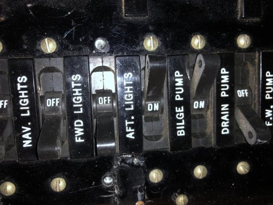
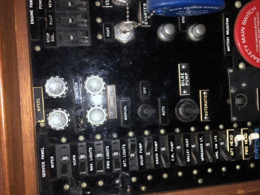
Problem two which I’m sure many of you experience readers thought about before you even started this paragraph realize either blew a fuse or maybe a breaker tripped? You probably know which however I don’t. I may have to go below which is fine and try to figure out which wire and then find and replace a blown fuse. My first thought however was maybe they’re easily accessible from the panel at my main salon NAV station. It appears that to access the back of it I will need to take 15 screws out? I took two screws out as you will see in another picture from the correct switch thinking maybe it would slide out and expose access to a fuse I could replace but nothing would move so now I’m wondering do I take the entire panel loose or do I go below and try to trace some wiring? Somethings telling me removing 15 screws and sliding that panel completely back is not practical therefore probably not the answer.

Before embarrassing myself in front of all of you learned experienced people I did a search in my manual as well as quite a bit online and the archives here. The only thing I learned is how little I know.
Hopefully I’ve done a reasonable job of explaining this and the pictures will help. I also wouldn’t mind you talking me off this ledge I’m on regarding my current sense of inadequacy?
 

Attachments

  • 1B1EA038-B44C-4E8C-B4E8-F29247B50AE4.jpg
    1B1EA038-B44C-4E8C-B4E8-F29247B50AE4.jpg
    69.1 KB · Views: 71
  • 57F1C58F-71B1-4FCB-8FB4-24D9C0126BB9.jpg
    57F1C58F-71B1-4FCB-8FB4-24D9C0126BB9.jpg
    95 KB · Views: 58
  • 146D8384-137F-41E8-97FA-B134B7443B4F.jpg
    146D8384-137F-41E8-97FA-B134B7443B4F.jpg
    176.1 KB · Views: 51
  • DD4E5C39-95EB-4096-82B0-03616AA536E3.jpg
    DD4E5C39-95EB-4096-82B0-03616AA536E3.jpg
    186.8 KB · Views: 55
Ohh wee. This is all 12volts, correct? I see a switch in one pix, do u want the lights switched at site? Or breaker turns all 3 on?

Seems like all 3 should be wired in parallel. Like my saloon. That means the closest 2 lights to the breaker will have 2times 3 wires each. The last of the 3 has only 2 wires plus and 2 wires neg to attach.
Still with me?

I would like to see the cables with red/black color code. Lots of white wire steers me to the aircraft forum. [emoji848]
 
First, you should have a multimeter so that you can be sure of what is going on. I really can't tell what color the wires are. You should be working with either Red/Black for 12v old school or Red/Yellow which is the current 12v standard. Red is always positive and Black or yellow is negative.

Now things get sticky. Did they wire the lights up in parallel which would be normal or did they wire them up in series?

I have more questions than answers at this moment.

The multimeter would tell us if we have any power or if breaker tripped. You can try flipping the breaker off and then back on but with out the meter you might not know if you have power.
 
Stop right now and get a marine electrician. There are several problems I can see even with the blurry pictures. There is solid wire. There are missing leads to the lights that should have been soldered and heat shrink insulated. The phantom spark was your warning. Again stop!
 
Stop right now and get a marine electrician. There are several problems I can see even with the blurry pictures. There is solid wire. There are missing leads to the lights that should have been soldered and heat shrink insulated. The phantom spark was your warning. Again stop!

:thumb::thumb:
 
Are you still enrolled in the classes?
If so are they DC electronics and AC electronics?
The AC electronics may get a little deep for you as it is mainly theory. The AC classes would be good but not until you get into LABs.

With DC try to think of it as water pipes and switches as on/off valves. Voltage is pressure and current is water flow. You must have a good DVM to test with. If you can try to draw out the circuits first.
 
Last edited:
I have some news for you.
The photo of the electrical panels? Those aren’t SWITCHES. They are BREAKERS. You don’t take any of the screws out to access the back. There are no fuses or breakers behind there: they ARE the breakers.

As already said, get some hands-on help from an electrician. You need a multimeter to check the wires for positive or negative voltage. Don’t ever trust the wire colour to indicate anything.
 
I really have nothing to add. But tungsten bulbs that you were using don't care about POS and NEG. But most LED bulbs do. So you might use a meter and say I have 12V but the LED will not work. In that case POS and NEG need to be changed out.

A meter will be your best friend in this. Use you tube or take a class on how to use a meter. I have seen people blow them up by not setting the correctly.

Here is a good book to own! https://www.amazon.com/Boatowners-M...517266&sprefix=boatowner's+mech,aps,67&sr=8-1 By Nigel Calder
 
Last edited:
Here is a chance to pick up some new skills. There are books available on 12 volt boat systems. A test light or multimeter wil be a big help for you.
All your circuits should go through your breaker panel or a fuse as you said. Probably your panel in this case as you called them switchs. When working on your lights the breaker should be in the off position to avoid sparks and overheating.
Make sure none of the wires are touching each other and turn on the breaker. Touch the leads of your test light to a pair of wires from the same hole. If it lights up then you have voltage and are good. If it doesn't light you'll need some local help.
To wire a light and switch you need one wire from the ceiling hole to go to one toggle switch terminal and a separate wire from the other toggle switch terminal to the bulb. The other wire from the ceiling goes straight to the bulb.
When you have that wired up turn on the breaker and you are good to go.
One more thing. Some LED lights need the plus and minus voltage hooked up in a certain way. If your test light works, but he LED doesn't, switch the wires from the ceiling to the ligh fixture.
Hope this helps. DC circuits as we use them on a boat are pretty easy to understand (until they're not). Sometimes we all scratch our heads.
 
I don’t think it’s all gloom and doom, you’re not the first person to realize they should have made a little sketch of how things were hooked up before they took it all apart.
It’s possible there’s some connections hidden in the headliner. Also adding to the dilemma is that these Taiwan boats don’t follow a color code that well, especially after decades of owners add and subtract equipment.
It looks like one of the lighting breakers is off. Maybe tripped? Reset it and see if your other lights come back. I see essentially two wires through the headliner in the middle position. Hard to say what’s positive or negative, but many times when the wires are white and black, the white ends up as positive. When that happens, it should be marked with red tape or heat shrink if possible.
Get a meter. It’s not hard to use. Set it for dc volts. Put the black lead on the wires that are connected together in that butt splice and the red one on that other wire poking out. If the breaker is reset you should see either +12 volts or -12. Or whatever your voltage to the panel is. This tells you polarity. If it reads minus 12 then swap the leads till you see plus 12 volts. When you have plus 12, the wire on the black lead is negative, red one positive.
Negative goes straight to the light bulb, positive goes to the switch and then from the switch to the bulb. Some fixtures rely on the fixture body for ground side wire, hopefully you have an actual place to hook a wire.
 
Thank you.

That’s a very thorough and appreciated response. I’m going to do something a little different Leigh than I’ve done before and answer various questions that came through on different responses. I’ll be back to the boat in about 45 minutes and check some things suggested here.
 
More questions and answers to some of the responses.

I’m going to answer some of the questions in some of the responses and then ask a couple more.
1. Yes to 12 Volt
2. They must be in parallel given the fact that each one had to be turned on separately by its toggle switch. I looked up parallel and series end screenshot it diagrams of each which I have saved in a new file call boat electricity. I can see that coming in handy.
3. I’m no longer in the class at the junior college. I got a college degree 40 years ago, recently retired, and now I guess I am also a junior college dropout! It was 40 minutes each way for my commute and by the third class we had moved away from DC into AC and were using little kits to build circuits. That would have been good to understand I know, but I just didn’t see learning enough applicable to my boat situation to continue.
4. Someone pointed out that what I called a switch is actually a breaker. My panels have the label above the switch. The one that is in the off position and the picture is for the forward cabin. My set up is such that main salon and aft cabin and head DC all work from that particular breaker.
Now questions as a result of your kind replies.
1. Since those are breakers, does that mean there would not be a fuse blown somewhere between there and the lights? Are fuses and breakers mutually independent?
2. When three lights with individual toggle switches are in parallel set up, does that mean that in addition to the positive and negative being routed from a main line to each, the same needs to happen with each toggle switch? Keep in mind my challenge of a ceiling liner that doesn’t allow me to see the entire picture and I’m doing all I can to not poke bigger holes in it.
3. Given my initially successful bulb replacement and wiring to the one on the far right, but having the spark and the light to the right also go out at that point, can I assume that the source comes in to the one on the right first and my accidentally letting the wires on the center one touch and then blow right build mean the wiring goes in that direction? It’s possible knowing that is a correct assumption could come in handy.

To those of you who said get a qualified electrician I appreciate and understand that. I actually have one that is supposed to be there hopefully today for a different project and if I haven’t solve this on my own which I would prefer to do for numerous reasons, I’m going to enlist his help on this as well.

Thanks again to each of you!
 
Most likely the switches are breakers. If you look at the backs of them you should see a amp rating and a name just to be sure. There should not be any fuse in line with the light if the switches are really breakers. But one never knows.

I am a little lost when you mention the main line and switch. The switch should be in series with the light that it is controlling.
 
Ohh wee. This is all 12volts, correct? I see a switch in one pix, do u want the lights switched at site? Or breaker turns all 3 on?

Seems like all 3 should be wired in parallel. Like my saloon. That means the closest 2 lights to the breaker will have 2times 3 wires each. The last of the 3 has only 2 wires plus and 2 wires neg to attach.
Still with me?

I would like to see the cables with red/black color code. Lots of white wire steers me to the aircraft forum. [emoji848]

I am with you on too many white wires.
why are you saying in parallel 2 times 3 wires each? Are you counting the tail from each joined pair?

What I see on the first one is two black going into a smaller wire now connected to one wire of lamp and a single wire connected to the other on the lamp.
What I am not seeing (on the first wired) is a second set of two joined wires with the tail which is visible.
That follows to the other two lamps, there are hidden joined wires in the ceiling that need to be brought out as the connection may be broken to leap frog the +/- from the first (that was made to work) to the 2nd & then 3rd.
 
Last edited:
I am with you on too many white wires.
why are you saying in parallel 2 times 3 wires each? Are you counting the tail from each joined pair?

.

YES.

Another note that needs repeating or highlighting. You appear to have all the necessary connection points now exposed. So, IF a wire or cable somehow turns into a different color mid stream, I would want that understood or fixed. DO not accept mid-route wire splices, or connections that have no direct access.
This may result in you getting some 16-2 BOAT wire and redoing the system; then, for sure, it will be understood. Just the 3 lights on this circuit, correct?
 
The last of the 3 has only 2 wires plus and 2 wires neg to attach.
Dave your last reply to my post established the 2-3 wire, The quoted should read one neg, one positive as it is at the end of the run (unless the circuit continues to feed others)
I am sure we see the same, stated different?
 
I really have nothing to add. But tungsten bulbs that you were using don't care about POS and NEG. But most LED bulbs do. So you might use a meter and say I have 12V but the LED will not work. In that case POS and NEG need to be changed out.

A meter will be your best friend in this. Use you tube or take a class on how to use a meter. I have seen people blow them up by not setting the correctly.

Here is a good book to own! https://www.amazon.com/Boatowners-M...517266&sprefix=boatowner's+mech,aps,67&sr=8-1 By Nigel Calder

This book will be far better than the class you took, if you want to learn how basic DC electrical works this is definitely something you want on board.
 
Dave your last reply to my post established the 2-3 wire, The quoted should read one neg, one positive as it is at the end of the run (unless the circuit continues to feed others)
I am sure we see the same, stated different?

Yes, my wording was awkward. I was trying to establish how many total conductors get terminated together. So the end light has two connectors, one each POS and NEG, and each connector has two wires in it.

Also, I was ignoring the switches.... I asked a question about how the switching was desired. In my saloon, I have wall switches that work several at a time, and no switches exist at the lamps. In the subjects boat, he could do all or nothing on switching, using the breaker/switch. OR, leave the breaker on and reach for the individual switches. Working with those switches does complicate things just a bit. But, we will get thru this..
 
Thanks Dave, I think the old and new lights each has a toggle switch in the rim is what I saw. I still would like to see the wires pulled out where the connections are. I think that is the "fuse" that blew, a pulled apart connection in the ceiling at the end of those single visible wires.
 
It would be best to determine whether the wire pairs leading to each lighting fixture have voltage before ripping down the headliner.
 
To those of you who said get a qualified electrician I appreciate and understand that. I actually have one that is supposed to be there hopefully today for a different project and if I haven’t solve this on my own which I would prefer to do for numerous reasons, I’m going to enlist his help on this as well.

Thanks again to each of you!

What did the electrician say?
 

Latest posts

Back
Top Bottom