wkearney99
Guru
- Joined
- Feb 17, 2018
- Messages
- 2,164
- Location
- USA
- Vessel Name
- Solstice
- Vessel Make
- Grand Banks 47 Eastbay FB
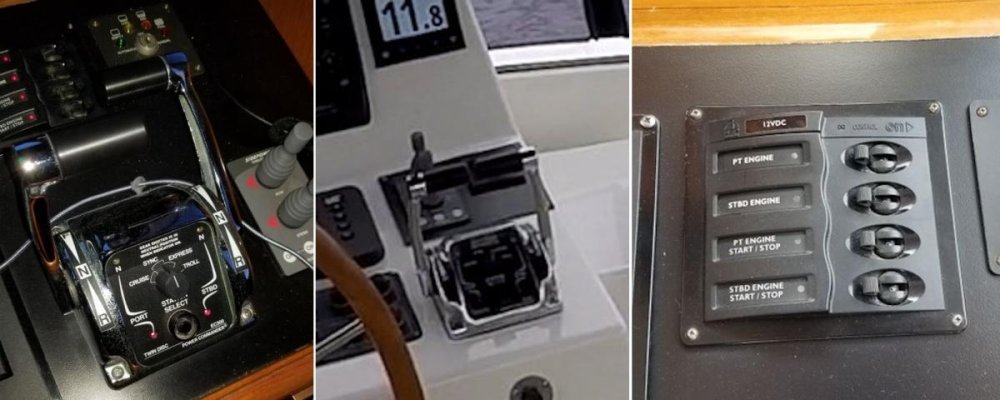
Anyone know what flashing lights on an EC300 Power Commands engine/transmission controls mean? I've got a boat set up with two of them and two Caterpillar C12 engines with Twin Disc transmissions.
One of the stations seems to have developed a problem. The usual way to change stations by tapping the 'Station Select' button no longer seemed to work. It'd just cycle rapidly back/forth between the two stations instead of switching. I suspect that it might be the Station Select button on it has gotten stuck. I disconnected the flybridge station (big cable connector into the bottom of it) and the boat runs fun with just the lower station control.
I notice the remaining station is flashing the yellow neutral lights.
It appears to be flashing 3-2-2? Anyone know what error condition that indicates?
https://youtu.be/U8DaahJvbRU