Collapsed motor mount?

The friendliest place on the web for anyone who enjoys boating.
If you have answers, please help by responding to the unanswered posts.

CharlieO.

Guru
Joined
Sep 21, 2020
Messages
1,558
Location
Lake Champlain Vermont, USA
Vessel Name
Luna C.
Vessel Make
1977 Marine Trader 34DC
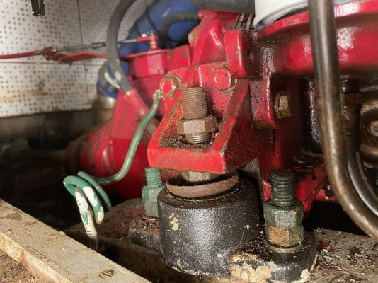
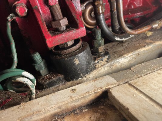
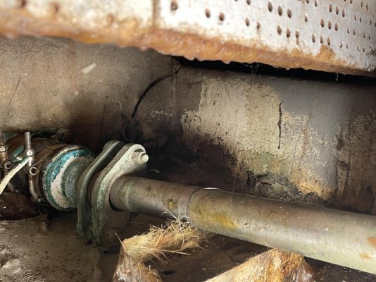
I believe I have a misalignment of the running gear due to a collapsed motor mount.
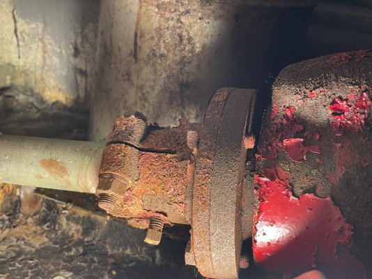
At the end of last season I had dock mates commenting that my bilge pump was running more often. I know my water tank had sprung a leak but I’m not convinced that was the only source of water. I think my shaft log/tube leaked a bit too prior to this issue. I think this misalignment may have worn a more prevalent hole in the tube that was more than likely at the end of its service life.

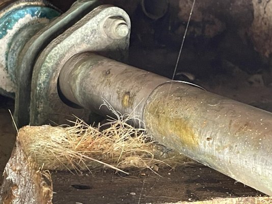
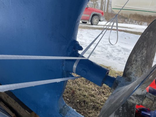
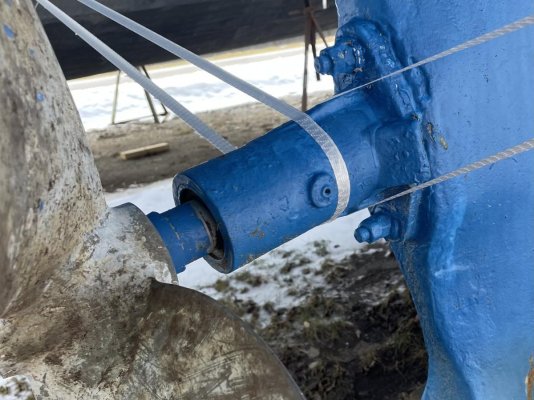
So I guess I will need to replace the motor mounts, pull the shaft and tube and replace cutless bearing on the prop end. Is there another bearing on the gear box side?

Any thoughts or comments before I undertake this project? I have contacted someone via PM on this forum that offered their experience in having this done by a yard. I will follow up more with them via phone call once I know what questions to ask. I will be doing this work myself.

I did pull the water tanks and had them repaired and pressure tested.
 

Attachments

  • IMG_2219.jpg
    IMG_2219.jpg
    189 KB · Views: 55
  • IMG_2220.jpg
    IMG_2220.jpg
    181.3 KB · Views: 41
  • IMG_2221.jpg
    IMG_2221.jpg
    170.7 KB · Views: 34
  • IMG_2222.jpg
    IMG_2222.jpg
    180.5 KB · Views: 30
  • IMG_2223.jpg
    IMG_2223.jpg
    168.6 KB · Views: 41
  • IMG_2224.jpg
    IMG_2224.jpg
    120.8 KB · Views: 31
  • IMG_2225.jpg
    IMG_2225.jpg
    148.1 KB · Views: 33
If you feel like attempting it...replacing these isolation mounts are pretty easy on a single engine vessel as access is usually good'

I measured each of the 4 mount heights and replaced one at a time. The engine will balance OK on 3, after loosening all the top nuts all around and with a good long pry bar, I was able to slip a new one under each of the 4 spots. My engine had the mounts on the engine, not on the transmission so I cant say how that may work.

I think there is a bearing at the top of the shaft log as the prop shaft didn't just slide right through, but after a bit of twisting I managed to get it through. That was because I did not replace the top cutless bearing. If you do replace it, it should be a much easier reassembly.

Google/you tube and you might get some better tips there too.
 
Last edited:
The engine mounts on the engine or on the transmission, it doesn't matter.
What does play a big role for replacing is, can you unscrew the threaded rod from the motor mount?
This is not possible with several models and then you have to lift the motor much higher.
That's how I did it, you have to have a solid floor.

CtKsHVa.jpeg


Wx0wwiH.jpeg


Mvg,

Pascal.
 
The engine mounts on the engine or on the transmission, it doesn't matter.
What does play a big role for replacing is, can you unscrew the threaded rod from the motor mount?
This is not possible with several models and then you have to lift the motor much higher.
That's how I did it, you have to have a solid floor.


Mvg,

Pascal.

I believe I should be able to unbolt the mount from the engine block and reassemble with the new mount.
 
I believe I should be able to unbolt the mount from the engine block and reassemble with the new mount.

One possibility, on my Lehman engine, I was able to slip all the old mounts out with just a pry bar for each corner.... I don't remember for sure, but I think I chose replacement isolators where the threaded part was separate to make it easier.

When I did the isolators on my 3208"s in my sport fish, to lift the engines, I used a 4by6 spanning the engine hatch with 2 holes drilled and threaded eye bolts, greased with big washers and nut on top. With a long closed end wrench, I was able to raise the engine up with one finger. Each bolt a little at a time and to do the job really only needed to raise the engine a few inches.
 
Several things don't look right in the pictures, if I am seeing them correctly.

- The shaft is tight/rubbing against the top of the shaft seal. This suggests the engine is too high, not too low. This is just the opposite of what you would get with collapsed mounts.

- The engine mount nuts have come loose and backed off. Or did you do that? We can't tell if the upper nut has worked its way up, or if the lower nut has worked it's way down. But either way, the lower nut appears to be at it's lowest position, yet the shaft is still positioned way too high in the stern tube and shaft seal.

So as it stands not, it appears from the mounts that the engine is as low as it can get, yet from the shaft and shaft seal it appears to be way too high. So I think something else is going on here, probably some sort of sagging in the hull. Were the pictures taken with the boat hauled and blocked, and does the shaft to seal gap change when the boat is floating? Unless a boat is REALLY solid, there will be some flexing which is why people say to always align in the water, not on the hard. But what we are seeing here seems excessive.

I definitely agree with your observations. The shaft was high in the packing while floating in the slip also. I noticed that when I was trying to track down the water leaking into the bilge.
It was not like that when I adjusted the packing last.

I agree that it looks excessive and that's why I need to address this.

When we've had the boat out cruising I never noticed any excessive vibration. But only noticed this after our last cruise and didn't take it out again before hauling out for the season.

I have not loosened or moved any nuts on the mounts yet.
 
I believe I should be able to unbolt the mount from the engine block and reassemble with the new mount.

When I've done this, I disconnect the propeller shaft from the transmission coupling (since you're doing cutlass bearings and the shaft needs to come out anyway) instead of unbolting the isolation mount brackets from the engine and transmission. With all bolts loose, I lift the front and do both sides and then do the back. It's usually pretty easy to build a wood frame (looks like half a saw horse) that sits on the stringers and over engine floor, and uses a "come along " or 2" load binder to lift.

Ted
 
Last edited:
Go to my blog, grandbankschoices, and you can see motor mounts being replaced on my 36GB and also running gear on a 42 GB.

Unless you just want to do it, take it to a yard. Mounts are easy, everything else is a bitch.

You can't just say the motor is high. Might be, or front might be low, teter- totering the rear. Back mounts hold engine and trans so they tend to go first.
 
Charlie,
Tell me about the leaking water tanks. We had this problem at the end of last summer and I'm about to pull them. Who fixed them and with what? Inquiring minds want to know.
Al
 
Charlie,
Tell me about the leaking water tanks. We had this problem at the end of last summer and I'm about to pull them. Who fixed them and with what? Inquiring minds want to know.
Al

Just one was leaking but I pulled both of them and brought them to the local welding shop for repair. The leak was on a seam/corner at the bottom of the tank. Stainless steel tanks. Had them pressure test both tanks.
 
FWIW, I did mine a year or so ago. They appear to be the same mounts as mine.


1. I disconnected the shaft from the xmsn flange and pushed it back a half inch. This is critical, as you'll see later in this post. If the shaft is really hard to push back, you may have to loosen the shaft packing - it resists shaft movement.


2. I removed the upper nuts completely, then raised all the bottom nuts to the highest position.


3. Then I used a small hydraulic bottle jack to raise one corner so the engine was above the top of the mount threaded rod, and removed that old mount. It only took a small amount of lift on the jack to get the corner I was working on to be raised above the old mount threaded rod bcs the other 3 mounts were already at the max "up" position.


4. After removing the old mount from the stringer and the engine, I replaced it with the new one, with the bottom nut already at max "up".


5. Repeat this all around.


6. Then, if possible, put the boat in the water for 24 hrs or longer. This will allow the boat to be in it's natural shape for the alignment. It's ok if the boat is on the hard, you just should do a realignment check once it's back in the water.


7. IMPORTANT: The shaft should be "hanging" in the center of the shaft log at this point, or it may be hanging low, toward the bottom. This is where I discovered my alignment had been off. My shafts, too, had been at the very top of the shaft log in order to be aligned with the engine. It was wrong. Once I disconnected the engine, the shaft hung low, on the bottom of the shaft log. This is because the shaft is only supported by the cutless bearing 10 feet aft of the shaft log. It's own unsupported weight forward of the cutless has to be accounted for.


8. You lift up on the shaft till it's centered in the shaft log, then use shims to hold it there. Assuming your cutless struts are straight and undamaged, and the cutless bearings are relatively new, this is where the mfr intended the shaft to come thru the log - in the center.


9. Now, adjust the engine mount lower nuts till your eyeball tells you the shaft is really close to mating perfectly with the xmsn flange. Insert the shaft-to-flange bolts and use them to pull the shaft toward the xmsn flange until there's a tiny bit of light between the two.


10. Now use a feeler gauge to check the differences in the gap at the 12, 3, 6, and 9 o'clock positions. Adjust the lower mount nuts all around as needed to get the engine's tilt angle (fore and aft). Use a 4 x 6 or pry bar to adjust the engine left and right to zero out the gap differential between port and stbd. It's tedious, and long the first time you do it. Record everything on a piece of paper - you'll forget and have to start over otherwise.


Once you've got the gap at 12/3/6/9 to zero (tolerance is supposed to be something like .003" max gap differential I think), use the bolts to pull the shaft up against the xmsn flange, and finger tighten the shaft-flange nuts. Now rotate the shaft/xmsn 90 degrees and check the gaps. Should be the same as it was earlier. Use your thinnest feeler gauge. Again, get it all as close as possible to zero. You may find the best you can get is .001" on the up/down, and .002 or .003 side to side, or some imperfect combo. I believe that's ok, ans what the tolerances were for.


Bottom line, replacing the mounts requires a careful realignment. It's work, it take a while, but it's not rocket science. And it sounds like it's an opportunity to get your shaft centered in the log. I might use this as a chance to replace the shaft packing, since it's likely worn at the top.


Good luck!
 
Post 1 shows SB aft mount, do you have a picture of the port aft and the two forward ones.
When I magnify the picture I see what looks like stripped threads.

I have to ask if it is possible it has been like this for some time, maybe a long time. Like maybe someone planned to replace it and that is why the nut appears to be loosened.
 
If you spin the shaft 180 degrees does it change position in the stuffing box? I am wondering if there are multiple issues including a not so straight shaft.
 
Post 1 shows SB aft mount, do you have a picture of the port aft and the two forward ones.
When I magnify the picture I see what looks like stripped threads.

I have to ask if it is possible it has been like this for some time, maybe a long time. Like maybe someone planned to replace it and that is why the nut appears to be loosened.

I'll take a closer look this weekend, I believe it just a bit shinier there because that where the steel from the bolt on part to the engine used to reside.
 
If you spin the shaft 180 degrees does it change position in the stuffing box? I am wondering if there are multiple issues including a not so straight shaft.

That is a good point, I'll check that this weekend, I don't believe the shaft is bent unless it happened to stop in the same place from the first time I noticed it. It also turns smoothly and consistently by hand during the rotation.
 
There is a formula for holding up the shaft to get in position. You calculate the weight of the hanging part of the shaft and then pull up half of that weight to get the shaft centered. Then align the engine to the shaft. Do another alignment after a couple of days in the water. The formula has been discussed here before but I don’t remember exactly what it is.
 
Greetings,
Mr. C. Somehow doesn't make sense to me. Say the hanging part of the shaft weighs 5lb. If you pull up with 2.5lb, the shaft wouldn't move at all. I think you would need to apply 5lb to get the shaft to move. Perhaps pull shaft up and "eyeball" the shaft in the center of the shaft tube?????

This is part of an article from Professional Boatbuilder on shaft alignment. Written by Steve D on shaft alignment. I would take his thoughts to the bank any day.

For example, 4′ (1.2m) of 2″ (51mm) shaft weighs 42 lbs (19 kg), divided by 2 is 21 lbs (9.5 kg), plus the weight of the coupling—which we’ll say is 22 lbs (10 kg)—equals 43 lbs (19.5 kg). Lifting 43 lbs at the coupling end of the shaft will negate the effect of the droop. In practice, the droop is negligible for small-diameter shafts and for shafts whose unsupported overhang is comparatively short, making the above procedures unnecessary. For long spans and heavy shafts/couplings, those steps are worth the effort.
 
Greetings,
Mr. C. I don't think all that ciphering is necessary in this case. Lift up the shaft until it appears centered in the stern tube support it in place and align motor to that.


Might be better if rubber tube connecting stuffing box to stern tube is slid forward to better see alignment. Stuffing box should self align.


Edit: Mr. J 15's (post #12) step #8 describes my poor description perfectly. Also agree with Mr. J 15. Replace shaft packing AND rubber tube. Clean up stuffing box housing.
 
Last edited:
Greetings,
Mr. C. I don't think all that ciphering is necessary in this case. Lift up the shaft until it appears centered in the stern tube support it in place and align motor to that.


Might be better if rubber tube connecting stuffing box to stern tube is slid forward to better see alignment. Stuffing box should self align.


Edit: Mr. J 15's (post #12) step #8 describes my poor description perfectly. Also agree with Mr. J 15. Replace shaft packing AND rubber tube. Clean up stuffing box housing.

Doing some math and lifting the hanging part of the shaft is the proper way to do it, no question. Eyeballing it is ‘probably fine,’ most of the time, on these small boats. But to assume the shaft tube & strut bearings were perfectly aligned during the build is quite optimistic.

A combination of the two methods, with a healthy does of ‘does what I’m doing make sense’ is probably best path forward. Don’t necessarily need to hire them for the labor, but getting the eye of an experienced person on-site would seem sensible to me, given the number of issues being spotted in a couple of photographs.
 
Greetings,
Mr. c. OK. The math. Does one measure the overall length of the shaft end to end or from the point where it exits the cutlass bearing at the aft end? Does one take into account the weight of the prop which acts as a counterweight because it is beyond the cutlass bearing? Also notice the shaft appears to be sitting at about a 25 degree angle off horizontal. THAT will affect weights, as well. Numerous parameters to consider if one wants to get the numbers correct.


With a 2" shaft posted as an example, 1' of shaft weighs about 10.5 lbs. Mis-measure by 3" or 4" and your weight is off 3 or 4 pounds.
Add to that your observation that "... to assume the shaft tube & strut bearings were perfectly aligned during the build is quite optimistic."


Bottom line IMO is simply does the shaft sit (while supported) in the middle of the stern tube? Weight has little to do with centering.


My own opinion is the "math" complicates what should be a fairly straightforward but fussy/time consuming project. By eye will work until it becomes necessary to use the feeler gauges.


KISS-Keep it simple sailor.
 
Last edited:
When I repowered my old Mainship many years ago, the installers lined the engine up to the existing shaft. It was way out of whack.
The marina mechanic was called in to get it all back in line again (it was out from Mainship's original build).
He pretty much did what RT described. He moved the shaft around until he got a feel for it being centered in the stern tube. Then he moved the engine accordingly until it was close. Then he used feeler gages between the coupling faces until it was within.002".

(the mechanic only had about 20 years' experience at that time)
 
Jay. What did you see, not what you were told was wrong with the original build.

Was the shaft wobbling, was there unusual wear. On the hard, was it difficult to turn the prop by hand?

I do not have experience with a mis aligned shaft and would like to know what people see. On my previous GB36 I had to uncouple the shaft in order to pull the tranny. I could turn the shaft by hand easily. When bolts were removed the shaft did not drop below the trans coupler. On assembly feeler gauges were used as a check. It spun freely by hand after initial sticking from sitting was overcome. All work done in water and engine ran in gear to see no wobble.
 
The aft end of the single engine was almost 3/4 of an inch to the starboard side of the centerline. That meant the mid bearing was approximately 3/8 of an inch off center.
I unbolted the mid bearing from the bulkhead and remounted it on center after the rest was lined up.

I believe the reason it wasnt noticed originally was because it had a bronze prop shaft that was flexible enough to go un noticed. I had changed to an Aquamet shaft to handle the added horsepower and because it was much stiffer it caused a vibration. ( thats my theory )
 
Agree with Tanglewood, you should have adjustment above and below engine bracket on the mount stud.

This article on alignment of both engine and shaft may be helpful https://stevedmarineconsulting.com/the-ins-and-outs-of-engine-and-shaft-alignment/

As well as this one on motor mounts https://stevedmarineconsulting.com/motor-mounts/

Thanks for the articles Steve, lots of information there. I will be doing my best to do a quality job on this endeavor. The other three engine mounts are double nutted closer to the center of the stud as they should be, that is why the one I showed caught my attention.
 
Presume that is a Lehman. Suggest paying attention to the bolts from the mount attaching to the engine/tranny. I had a case where they all sheared because the hardness rating for those bolts was well under spec. There should be a number on the head of the bolt.
 
the boat is in the shipyard, the hull is deformed, it is impossible to adjust engine mounts (even new ones) in these conditions ...
 
In the yard rough adjustment needs to be done with the final after awhile of the boat being back in the water.
 
Back
Top Bottom