More solar questions....

The friendliest place on the web for anyone who enjoys boating.
If you have answers, please help by responding to the unanswered posts.
And on the other end, I thought you were going to feed the DC system through the DC panel, either through a sub breaker or through the main panel breaker. Your wire should be big enough for even the main breaker (often 50-60 amps). But maybe if you are feeding the main breaker, you want a disconnect and that 30A should work fine.


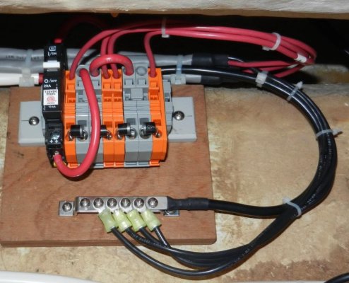
I was able to get down to the boat today for a couple hours to try and figure out exactly where I could run wire. I also took a closer look at my DC panel in the Pilothouse and found an unused breaker. It was originally for a water maker than the PO had installed and then removed after finding he just didn’t use it. That breaker is a 50amp breaker and the breaker for the panel as a whole is 100amp.

So if I was to take the positive feed from the controller and connect it to the 50amp breaker where the output for the water maker was, then that should back feed the battery as long as the breaker is on. I think I like this idea better than adding another surface mount breaker.

I ran a small line where I am going to have to run the 10 AWG wires from the panel on the pilothouse roof to the controller which will be behind the DC panel. That should make it easier to run the wires later.

Here is a stupid electrical question. How big a wire do I need from the controller to the 50amp breaker? I believe the idea is that the breaker needs to protect the wire. I think the panel has a 6 AWG wire that runs from the panel for about 3’ to the positive bussbar where it connects to a 70mm cable which runs to the battery. That would make sense since the panel breaker is a 100amp breaker. For a 50 amp breaker, what would be the largest wire that I would want to use to run the 3’ from the controller to the breaker? I would tend to use a 10 AWG wire, but am I correct that a 50 amp breaker would protect a 12 AWG wire and therefore would also provide plenty of protection for a 10 AWG wire.

Dang I hate being so dense!
 
Just keep in mind that back feeding through the 50A breaker may well cause confusion for people operating your boat, or working on your boat. One would normally turn off the main 100A breaker to kill power to all the panel loads, and expect it to go off. Depending on how much sun and what loads are on, turning off your main breaker will result in no change at all to you power, or no power, or somewhere in between. Any operator needs to know to turn off the solar breaker first, then the main breaker if they really want to turn off power. This won't be an issue for you because you know the boat, but anyone else will need to be trained and relied on to do the same.

If you backfeed to the battery side of the main breaker, then operationally the electric panel will behave as one might expect.
 
Good point twisted. The only downside there is that I can’t then disconnect the panel and controller without also disconnecting the DC panel. I will give it some thought....
 
Good point twisted. The only downside there is that I can’t then disconnect the panel and controller without also disconnecting the DC panel. I will give it some thought....


And hence the practice of a dedicated breaker/switch on the controller output.
 
The breaker(switch), between panel and controller, makes a convenient way of disconnecting panel, without having to mess with wires. If you run wires aft from panel, where will you mount the controller? If in the lazzerette, does the controller have a remote, making it easy to monitor, rather than getting into lazzerette.
There are several ways of getting wires aft, all of which are more trouble, than I chose to do. My install, may not be the most efficient but it works, and works well. If the panel was on a pole with a tracker, now that would be good, but it is all a bit of a trade off. There is more than one way to skin a cat.

I was looking yesterday at how I could run a pair of 8 or 10 AWG wires from the PH roof to the aft lazarette. I think the best route would be from the roof, under the PH headliner, and then down the wiring chase that is behind the PH bench and refer. From there it would get tough as the wires go back to the ER DC panel and along the base of the port water and fuel tanks. The tough part I think would be getting the wires from the bottom of that wiring chase back to the ER. The opening is small and already packed with lots of wiring.

Once in the aft lazarette I'd mount the controller on the bulkhead separating the ER from the lazarette on the Stb side. I'm going to use the Victron SmartSolar controller which can be controlled via its internal bluetooth for monitoring and setup.

That would be the "best" way to do it, particularly if I was able to run 8 AWG wires aft. However like you, it is more trouble than I want to do right now. Because of that, I'm going to follow your lead and backfeed it from the PH. If I decide to change it later on, I can always do it. I certainly am in the camp of "good enough is good enough for me". It was your installation that provided the inspiration and encouragement to do this. BTW, I am going to use the bluetooth MPPT controller partly to just avoid me having to spend the money on another wire and a control/display module and I won't have to cut another hole in the pilothouse teak anywhere.

Since I have that unused 50 amp breaker in the panel for the watermaker I think I will use it. I will run the power wire from the controller to the load side of the breaker. Then that breaker will disconnect the panel as well as protect the wire.

Given Twisted's warning about someone potentially not knowing about the panel when working on the system I may do a couple things. The best would be to swap the 50amp breaker with the breaker at the top of that column. I could then move the bar that is on the power side of that column down to separate that breaker from the panel. Then it is just a matter of adding a separate wire from the breaker to the positive buss. However, it would also mean re-labeling the backlit breakers. I've never done anything like that so am not sure what is involved.

The other option would be to simply put a cover over the breaker switch. If I, or someone else was going to be working on the boat, I'd just open the breaker and close the cover. I could even do what I do with my macerator switch and zip tie it closed.
 
Some decision made...

I have ordered the 365W LG panel. It will likely be ready for me to pick up this Friday, actually a couple weeks ahead of when I'll actually be ready to install it. This weekend I have a meeting all weekend and then work keeps getting in the way of the important stuff.

As I mentioned in my last post, I think I have figured out how I am going to wire the backfeed into the DC system.

I've got a message to Compass Marine to see if he can source the Victron SmartSolar MPPT 100/30 controller for me. I will also get the Scanstrut deck gland from him once I am sure of the right size. I forgot to ask him if that deck gland can be mounted with 4200 intead of screwing in the roof.

I need to get some SS hardware and some 10 AWG wire and the appropriate crimp terminations for it. All the wire and terminals I have handy is smaller.

I also think I will use the 3M 5952 VHB tape to mount the L-Feet. That should give adequate strength and flexibility The base of the L-Foot I am going to use is 2 x 2". I can get 2" tape and trim it slightly to set the edge of the tape back slightly from the edge of the L-Foot base. I can then seal the edge with 4200 it will protect the tape from water and dirt.

So, that is the plan and I am sticking to it. At least until I change my mind. :whistling:
 
You may be able to run wires from pilothouse ceiling straight back to where engine vents are, down into engine room, then back to rear bulkhead by water heater, there is a chase there where wire could run into lazzerette. Dale, on Silly a Goose, might be one to ask. I have run wires from DC panel thru Guest Strm, it is a bit of a pain. Also, from MFD, down behind Stbd side hanging locker, thru head, and aft from there. Twice for transducers and once for water maker, oh yeah and once for camera to engine room.
 
I've got a message to Compass Marine to see if he can source the Victron SmartSolar MPPT 100/30 controller for me. I will also get the Scanstrut deck gland from him once I am sure of the right size. I forgot to ask him if that deck gland can be mounted with 4200 intead of screwing in the roof.

Dave,

If Rod cannot help you on this, I suggest you look at:

https://baymarinesupply.com/solar-wind/charge-controllers.html?manufacturer=243

https://baymarinesupply.com/solar-w...smartsolar-mppt-100-30-charge-controller.html

I have bought many items from them over the years, along with my new Victron 100/50 Smart Solar controller, and have never had a complaint.

Make sure you select the SmartSolar one if you want bluetooth control.

By the way, I selected these (https://www.amazon.com/gp/product/B0111RNZDY/ref=oh_aui_detailpage_o00_s00?ie=UTF8&psc=1) for the reason you stated regarding not wanting to use screws. I intend to use 4200 or the same 3M tape you mentioned. Then all I will need is one hole for the actual wires, which I will seal with butyl tape (which I bought from Rod). All butyl tape is not equal, by the way. The tape Rod Collins sells is very good quality.
 
More mount questions

I picked up my panel today as well as some additional hardware I had ordered from Platt Electric. Fortunately, the panel fits nicely in the back of my Explorer.

The Unirac L-Foot mounts look like they are going to work well. I took some photos of how I anticipate using them. The bolts are just what came with the feet. I have some 316 SS bolts and washers coming. I'm going to use Nylock nuts but the only ones I could find were 304 SS. Probably not a big deal.

I knew the L-Foot brackets had a serrated back, which will actually help a lot for my application as the two serrated backs will not tend to slide against each other. However, the bottom of the foot portion is also serrated. I had planned on using 3M VHB tape on the bottom to mount these. That tape works great on smooth surfaces, but I don't think it works well on rough surfaces. So, instead of the tape I am back to thinking about using 4200 to affix the feet. I'm open to opinions.
 

Attachments

  • IMG_20180323_161606.jpg
    IMG_20180323_161606.jpg
    87.3 KB · Views: 44
  • IMG_20180323_161644.jpg
    IMG_20180323_161644.jpg
    82.6 KB · Views: 43
Dave. How many of those brackets will you be using. Seems I read 2 per side, for a total of 8, which sounds good. If you are only using a total of 4, I would be a little nervous.
 
wiring connections, above or below?

Another question I have. The panel has MC4 connectors on the wires coming from the junction box. These wires are actually 1 meter long so I have a fair bit to work with. Initially I had planned on connecting them above the PH roof to the wires that will go down into the boat and be connected to the controller. Given the 3' of length, I'm thinking about making that connection right under the PH roof. This would leave no connections exposed to the weather and leave less loose wire.

I'm trying to think of reasons not to do this. The connection would take place right under the PH roof and be readily accessible by simply removing the overhead panel in the PH which are simply attached with heavy duty hook and loop. So if I need to access those connections it would be easy. It would make removing the panel a bit more difficult because I would then need to open up the deck gland to get the MC4 connectors back through the roof. However, I don't see needing to remove the panel unless there is some major issue.

Opinions and experience please?
 
That is what I did! I moved the horns, and enlarged the horn hole, and used it. Mounted horns off to side of panel.
 
Ahoy,

I am following this thread with great interest as I am about to install solar panels on the pilot house roof of my Krogen 39.

I have purchased two Panasonic 330 watt (VBHN330SA16) panels.

(ftp://ftp.panasonic.com/solar/specsheet/n325330-spec-sheet.pdfand)

I chose these panels because they are slightly smaller than other panels of similar output and efficiency, allowing me to install two of them on the roof.

I intend to install them, in parallel, using AWG8 cabling, using 2 into 1 (AWG12 to AWG8) Staubli MC4 connectors, to a Victron SmartSolar MPPT 100/50 Charge Controller............
Any comments on the fusing, and/or my overall plan?

Look into adding diodes to the parallel wiring. If one panel is shaded while the other is not, the shaded panel can shunt power from the working panel, so you'll negate any advantage in parallel wiring. I have the exact same situation, and I did 4 24V panels in parallel because of shading. I used DIN mount junction connectors to make the connections and incorporate the diodes. It works as intended, I get pretty close to 1/2 the output when the 1/2 the panels are shaded.

The pic shows the junctions installed, the orange are just smaller wire size than the gray, and the gray ones have a jumper that connects adjacent blocks. The diodes are at the bottom, and the breaker to the left creates the disconnect for shutting the panels down.

DIN components sourced @ McMaster-Carr. Diodes from eBay.
 

Attachments

  • DSCN6139_crop.jpg
    DSCN6139_crop.jpg
    106.1 KB · Views: 51
Last edited:
Dave. How many of those brackets will you be using. Seems I read 2 per side, for a total of 8, which sounds good. If you are only using a total of 4, I would be a little nervous.

Only 4. LG is happy with 4 mounting points. The real question is how solid will the brackets be. Each base is 2" x 2". So that gives a total of 16sq-in of contact area for the 4200.

Now, I could use more. LG doesn't like you to drill into their frame (not that I think it would be a big problem). Even so, I could drill another hole midway on each of the long sides for a total of 6 mounts. Or I could use all 8 of the pre-drilled holes. They are 4" and 12" from each end of the long sides.

Every time I looked at it, I kept coming back to 16sq-in being plenty, but maybe upping that to 24sq-in might be prudent?
 
That is what I did! I moved the horns, and enlarged the horn hole, and used it. Mounted horns off to side of panel.

Yeah, I considered moving the horns, but decided that I'll just clear them with the panel. The clearance will give me close to the clearance that LG wants for their panels so they should stay relatively cool.
 
Only 4. LG is happy with 4 mounting points. The real question is how solid will the brackets be. Each base is 2" x 2". So that gives a total of 16sq-in of contact area for the 4200.

Now, I could use more. LG doesn't like you to drill into their frame (not that I think it would be a big problem). Even so, I could drill another hole midway on each of the long sides for a total of 6 mounts. Or I could use all 8 of the pre-drilled holes. They are 4" and 12" from each end of the long sides.

Every time I looked at it, I kept coming back to 16sq-in being plenty, but maybe upping that to 24sq-in might be prudent?

I expect LG is unconcerned with the attachment strength of the bracket to the structure. They would expect it to be extremely strong.

Their recommendation of 4 mounts reflects their confidence in the actual module strength.

Using 4200 to bond 4 brackets to a gelcoat surface may, or may not, be what they had in mind, but it isn't the basis of the 4 attach point recommendation.

I like those beefy brackets. I wonder if the 3M tape would work regardless of the serrations. It seems to have a sort of thin foam core between the adhesive on each surface. Perhaps that would mitigate the somewhat minor lack of smoothness. Perhaps a call to 3M customer service would help.
 
I have much more mounting area on much smaller panels. I would up the gluing area if possible. I`ve had no problems 7 years on, screwing brackets to the panel frame.
My first thought with those serrated feet was it significantly increased the gluing area for your choice of adhesive sealant. Adhesive tape may not give you that, if anything it might give less adhesive area.
 
Look into adding diodes to the parallel wiring. If one panel is shaded while the other is not, the shaded panel can shunt power from the working panel, so you'll negate any advantage in parallel wiring. I have the exact same situation, and I did 4 24V panels in parallel because of shading. I used DIN mount junction connectors to make the connections and incorporate the diodes. It works as intended, I get pretty close to 1/2 the output when the 1/2 the panels are shaded.

The pic shows the junctions installed, the orange are just smaller wire size than the gray, and the gray ones have a jumper that connects adjacent blocks. The diodes are at the bottom, and the breaker to the left creates the disconnect for shutting the panels down.

DIN components sourced @ McMaster-Carr. Diodes from eBay.


I personally believe that the shading problem is grealtly over rated. I have 4 panels, two set of 2 in parallel with the those sets connected in series. My Vmp/panel is about 32V. So when a shaded condition occurs, sure there is some power lost shown by a lower voltage at my Victron controller but no where near what many sites predict or the so called videos showing power lost with shade.

The video shading with a towel on top of a panel will disrupt power output. But actual real world shading does not have a rag placed on top of a panel. There is illumance on panels even in the shade. If the sun is out, there is illumance almost everywhere even in the shade.
 
Last edited:
I expect LG is unconcerned with the attachment strength of the bracket to the structure. They would expect it to be extremely strong.

Their recommendation of 4 mounts reflects their confidence in the actual module strength.

Using 4200 to bond 4 brackets to a gelcoat surface may, or may not, be what they had in mind, but it isn't the basis of the 4 attach point recommendation.

I like those beefy brackets. I wonder if the 3M tape would work regardless of the serrations. It seems to have a sort of thin foam core between the adhesive on each surface. Perhaps that would mitigate the somewhat minor lack of smoothness. Perhaps a call to 3M customer service would help.

You are right, LG doesn't care about the surface side of the mount, only what is attached to their frame and don't want me messing with it. :)

I read a very interesting report on the performance of VHB tape. It went over my head but they were talking about how different materials were high flow or low flow when it came to the tape adhering. I came away with the message that the tape works great on smooth, clean surfaces like metal or gelcoat. Very small scratches in the surface, such as achieved by a fine grain sandpaper can help, but the rough ridges are not a good mix.

I have considered using a belt sander with the appropriate belt to smooth out the rough serrations and then use the VHB tape.

Interesting about the VHB characteristics. Seems logical in a modern sort of way.

Well you certainly have enough material with those brackets to shave off the ridges.

I bought the adhesive mounts from RV Solar for mounting my two panels. The RV Solar brackets are nothing like yours. They are much thinner sheet aluminum. They have larger footprint for the adhesive (4"x1"), and a shorter maximum height by about an inch and a half. Though they aren't nearly as beefy as your extruded ones, I think they will do the job. I will use 6 mounts per panel in my installation.
 
I made 6 many brackets for each of my 275 watt panels out of aluminum angle. With the dimension of two by two where they hid my fiberglass hardtop and I use the 3M tape after reading of the use of this tape on RV parks the claim was they are good for at least 80 miles an hour down the road. It's only been 2 months but it's so far it is worked very well
 
Great ideas from everyone. Here is my latest solution. Essentially I am looking at taking two L-foot brackets to make a T-Foot. Then a 3rd L-foot to support the panel.

This gives 8 sq-in of contact area under each panel mount. If I use this brackets that have a serrated bottom, I’ll use 4200 to affix them to the roof. If I use a smooth bottoms bracket, I’ll use 3M VHB tape with 4200 to seal the edges.
IMG_0355.jpg

I received the Scanstrut deck gland in the mail today from CMS and he is sending me the Victron SmartSolar 100/30.

Now all I need a free weekend to actually do the install.
 
Dave: I used the 4200 and the nylock nuts and it worked well for me. BTW, you might think about having the lower bracket point inwards, i.e. make it a “U” on its side. That way foot is situated under the panel and I think it’s just as functional and provides a better sightline.

When you use the 4200, get prepared and think carefully how it will all go together. I masked the area off under the “foot”, and I had it arranged that the panel settled on blocks leaving ~0.125” gap between the foot and the substrate. That way all the 4200 doesn’t all squeeze out.

I should also add you only need to hold the 2 pieces of the bracket with one bolt, not two. That way the angle can be adjusted slightly if necessary.

Jim
 
By the way, I selected these (https://www.amazon.com/gp/product/B0111RNZDY/ref=oh_aui_detailpage_o00_s00?ie=UTF8&psc=1) for the reason you stated regarding not wanting to use screws. I intend to use 4200 or the same 3M tape you mentioned. Then all I will need is one hole for the actual wires, which I will seal with butyl tape (which I bought from Rod). All butyl tape is not equal, by the way. The tape Rod Collins sells is very good quality.

Hope you'll do a neater job on the install that those pictures on Amazon!! ;)
 
I have heard about the RFI from some controllers and that is a reason I will want to stick with a known manufacturer. (BTW, anyone experience RFI with the Victron?)

I have wondered about putting a switch between the panel and the charge controller. If the sun it out, and I need to disconnect the panel or controller, it might be nice to be able disconnect it.


It's a good idea with the switch but don't put one between the controller and the batteries.

Re: RFI, a few sailing friends bought their Chinese controllers on Amazon and they completely choked off the VHF, FM and AM. I have a Victron MPPT and there is no problem whatsoever. fb
 
Great ideas from everyone. Here is my latest solution. Essentially I am looking at taking two L-foot brackets to make a T-Foot. Then a 3rd L-foot to support the panel.

This gives 8 sq-in of contact area under each panel mount. If I use this brackets that have a serrated bottom, I’ll use 4200 to affix them to the roof. If I use a smooth bottoms bracket, I’ll use 3M VHB tape with 4200 to seal the edges.
View attachment 74557

I received the Scanstrut deck gland in the mail today from CMS and he is sending me the Victron SmartSolar 100/30.

Now all I need a free weekend to actually do the install.

Excellent idea!
 
Dave: I used the 4200 and the nylock nuts and it worked well for me. BTW, you might think about having the lower bracket point inwards, i.e. make it a “U” on its side. That way foot is situated under the panel and I think it’s just as functional and provides a better sightline.

When you use the 4200, get prepared and think carefully how it will all go together. I masked the area off under the “foot”, and I had it arranged that the panel settled on blocks leaving ~0.125” gap between the foot and the substrate. That way all the 4200 doesn’t all squeeze out.

I should also add you only need to hold the 2 pieces of the bracket with one bolt, not two. That way the angle can be adjusted slightly if necessary.

Jim


Good ideas Jim. There was a Practical Sailor article a while back that mentioned using a SS washer as a spacer to keep the 4200 from getting squeezed out. One advantage of the serrated feet is that there is a lot of contact area.

I also have thought about setting up the mounts so they are less visible under the panel on the forward edge. On the back edge, I was thinking about turning them 90 degrees. That way, I only have to loosen the bolt and it will act as a hinge so I can lift the forward edge to clean underneath it.
 
I finally got a free day to work on the boat. I ended up getting some L-Foot brackets that have a smooth bottom so I can use the 3M VHB tape. The back side of the brackets are serrated so to keep the absolutely flat on the bottom I used some 5200 to adhere them together back to back.

I started the wiring and was doing well until I realized I needed a couple of 3/8” ring connectors.

Here is the back of a part of my DC panel. The 50amp breaker (green arrow) was for a now absent water maker. I swapped it for the 30amp breaker (red arrow). I was able to shift the positive bar that runs up the left side of the breakers down one breaker so that the 50 amp at the top will simply be between the charge controller and and positive bussbar.

IMG_0357.jpg
 
I was a able to get part of a day to try and install that panel. The weather was good and tomorrow calls for wind and rain.

My wife was able to come out to help me lift the panel up on the PH roof and get it in place. Once there, the slope and curve of the PH roof became apparent. I had to do some adjusting to mounts so their base will sit flush on the roof. I used the 3M VHB tape and then (in the dark unfortunately) used 4200 to seal the edge of the tape bond.

When I got the panel in place I quickly wired it up just as the sun was about to go below the hills. I connected the Victron app to the SmartSolar controller and saw that the panel was putting out a whopping 4 watts just before the sun when below the hills. At least it tells me that it was basically wired up correctly.

I did discover that somehow I killed the saloon light circuit, so I need to figure that out.

I will try and take some photos this weekend.
 
Back
Top Bottom