OP
OP
HeadedToTexas
Guru
For those of you in the unswitched fused connections for bilge pumps, is fuse inspection per of your daily checklist? Do you inspect the fuses with a multimeter or visually?
I have also read of a motorhome owner that burned up his TOAD (dingy) due to an auto reset breaker in his line that charges / maintains his battery. I prefer the manual reset variety above auto or fuses.
I think an auto reset to the battery is not good. I suggested auto reset from battery to bilge pump. I have always considered a bilge pump essential equipment.
I would be interested to hear why ABYC does not approve.
Having a single circuit breaker for multiple bilge pumps is a bad idea. If one shorts and trips the breaker, you will have no power to the rest of them. Also, the circuit breaker would have to be rated for the maximum current draw of all the pumps running at the same time. That might not protect an individual pump and wiring.
Fuses provide a better solution for bilge pumps because they are available in a wider variety of ratings than circuit breakers.
Any circuit protection should be installed within seven inches (measured along the wire) of the source of power. Panel mount fuse holders are convenient and would be a good installation.
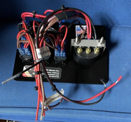
C lectric, you don't consider the relay an additional point of possible failure? Not questioning what you did but just curious because I am about to rewire my bilge pumps.
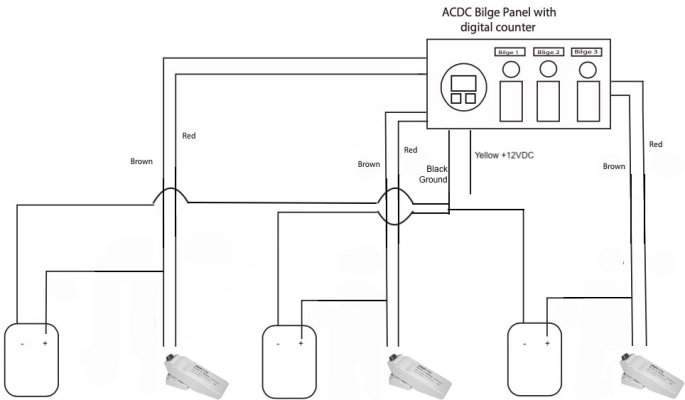
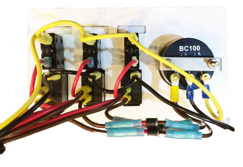
Here's where I will be when the soldering is done. The DC grounds will come back "all" the way back to the bilge pump panel. They are all basically right beneath the panel at our lower helm, so it isn't that far.