Complete water supply system overview

The friendliest place on the web for anyone who enjoys boating.
If you have answers, please help by responding to the unanswered posts.
How big a boat? How many people? Planned water budget for 24 hrs? What will your peak water flows in each line? Water flow rate, length, number of bends and valves sizes lines (pressure drop calculation). What components will be operating at the same time (total flow rate required)? A larger accumulator is ok if you have the space results if less pump cycles.
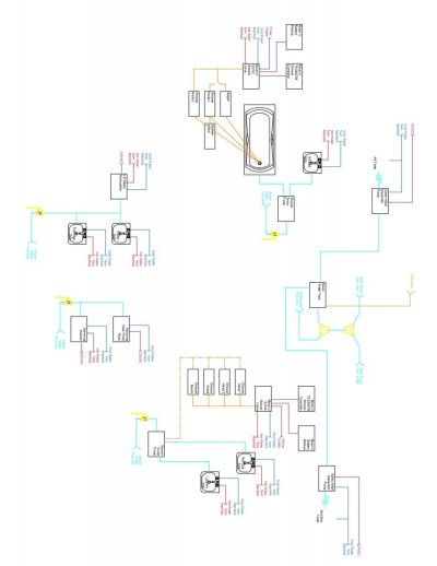
Seems very complicated. Hotter tanks can be run at temps above 120 F if you have a mixing valve to control temps to a delivery temp of 120. Makes for more hot water with a smaller hot water tank.
Do you have another drawing showing all of the drain lines, black water and grey water tanks. Electrical power drawing? Number of thru hulls and overboard drains. Controlling 7 small tanks as they pump down will be a pain if you do it individually. Filling will be difficult and could take some time.
What does the mid and aft galley maid pump do. They only have a cold water supply. Just some general comments.

No idea about water usage for 24 hrs.
Peak water flows depends on the number of people, but having two bathrooms does help limit this.

The size of the boat is 65', which will be 70' with the swim platform extension.
For normal usage 4 to 6 people.
Day usage, no overnight, usage 10 people

For controlling the 7 tanks, they will be linked, and as long as the valves are all open, will operate as a single tank. The filling will operate the same way as well. Dock water will go to a deck hose opening, water will flow into a manifold, and fill up each tank.

The galley maid pumps are the macerator pumps. They require, at least to my understanding, a water line in. Technically it is supposed to be sea water, but I am using fresh water.

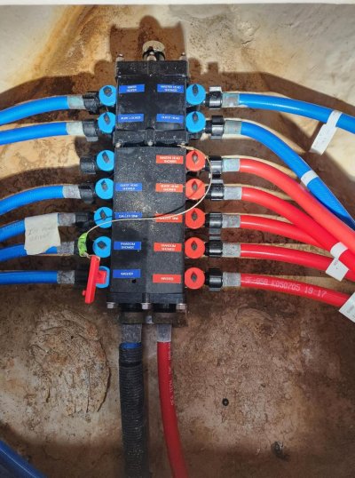
Attached is a photo of the waste system. There is no grey water tank, only a black water tank, which is overly large. It was a microphor waste system. It will be just a holding tank like a normal system. I thought about trying to get it out of the boat, but it is big pain in the butt.
 

Attachments

  • Waste System 11.29.22_page-0001.jpg
    Waste System 11.29.22_page-0001.jpg
    63.7 KB · Views: 13
and a pdf version of the waste system for better quality.
 

Attachments

  • Waste System 11.29.22.pdf
    109.9 KB · Views: 22
If the dock water fill is open, gravity feed, then I don't understand the connection to the pressurized part of the water system. Nor do I see a need for a check valve on the water fill to the tanks.


I think I understand what you are trying to do with the HW production part of the system, but I don't think it will work as desired.


First, I don't think you need three thermostatic valve in series like that. One should be fine. And this is the type of valve I was suggesting for the HW heater output. That lets the heater run up to 140F or so, while setting a delivery temp of 120F.


When there is a demand for hot water, it will draw in parallel through the HW heater, and all three of the heat exchangers, and the tankless heater. To whatever extent one of them is cold, you will be drawing cold water.


I think there are a couple of approaches to get what you want.


First is to use a HW heater that includes a head exchanger loop. You could connect that loop to one of the engines (no external heat exchanger required), but you would only have that one extra heating source. This is how most boats do it.


Alternately, you could plumb the heat exchangers in series and then them through the loop in the HW tank. You would need a circulating pump, and a control circuit to detect when one of the engines/gen is running and turn on the circulator. That would heat the water in the tank.


Third approach would be to again plumb the heat exchangers in series, but insert them into the cold water feed to the HW tank. When one of the engines is running, it would pre-heat water going into the tank. The funky thing with this approach is that it depends on the water in the tank already being hot. The pathological case is that you have cold water in the tank and an engine running. You would have to draw hot water (that would actually be cold) long enough to get enough pre-heated water into the tank to actually get hot water at the tap.


And last I can think of would be to again plumb the heat exchangers in series, but plumb that in parallel with the tank and have some sort of circulator that exchanges water between the tank and exchangers to keep the water in the tank hot. I haven't thought this one through, and the controls may be overly complex.


I'd suggest sketching out each of these and see what makes the most sense for your situation.


One thing I will caution is that the heat exchanger loop through some HW tanks is woefully undersized and will limit how much heat you can transfer.
 
I have also attached a photo of one of the manifolds I am using.


That manifold looks somewhat like ours.

Ours is SeaTech (now Watts) and appears to made up of individual valves somehow connected together. Or maybe ours is made up of a couple smaller manifolds -- one with 5 hot and cold each, the other with 4 colds -- bolted together.

FWIW, part of this confused me for a while 'til other owners got me straight. One of the cold lines -- I expected it to be an outlet on the manifold -- turned out to be a 2-way street. Input from shore water, but also output to transom shower (as marked on the manifold), the transom washdown outlet, and the engine room washdown outlet. As it turns out, that means I can use either the shorewater inlet function or the the transom washdown outlet as an injection point for compressed air when winterizing our system. Latter bypasses the inlet pressure regulator.

-Chris
 

Attachments

  • 20221125_135004.jpg
    20221125_135004.jpg
    192.9 KB · Views: 23
Last edited:
Just a comment on using the manifold/home run strategy rather than the traditional layout... we built a fairly large house about 3 years ago, I had done a lot of research on the Viega Manabloc system and decided not to go that route for a couple of reasons. The manifolds have had some leakage issues, the cost vs benefit didn't seem convincing and most importantly (for me), you can't run a hot water recirculation system.
After 3 years in the house, I'm happy with the decision. I like the instant hot water and I haven't had any need to isolate a particular fixture.
 
Don't forget a fresh water line with a carbon filter to the water maker so it can be flushed.
 
Coming from your tanks you just have a strainer which I assume is just a mesh screen to capture large particles. When we replumbed our boat we added a strainer, a basic filter and a carbon filter which then fed a UV water treatment light. That ensures that the water going into the system is sanitized. We also have RO systems for the kitchen and ice maker as you do.

Our first design also started out with full runs but we switch to a smaller main manifold that then fed branch manifolds. By doing this less pipe is used and the branch manifold become the local shut off.

Good Luck,
Bill
 
Just curious, when was the last time your plumbing system malfunctioned that wasn't due to either the pump or a leaky fitting? What else is there? OP put it out there for comment. Tribe has spoken on complexity. Up to the OP whether the input makes sense to him

The chances of me turning the correct valve when there over 50 of them scattered throughout the boat is akin to chance of my hooking up with Jennifer Aniston

Peter .

Two years ago when I replaced my water heater. Three years ago when I replaced my refrigerator with a built in ice maker.

The tribe may have spoken but they were not necessarily constructive.
 
complete water system replacement

Beverage and Beer | Beverage Equipment / Parts Distributor - Apex Beverage Equipment

SNDOG,

I woke up in the middle of last night thinking about this job - and being glad I didn't have to do it! - but also thinking about something that may be helpful. If you follow the link above, it will take you to the site of a supplier of tubing and accessories used in the beverage industry, which in addition to individual tubing are made up into bundles of different numbers of lines and different ID and OD, depending on what is needed. The bundles are simple sheaths that allow you to more easily get the tubes into a chase or conduit, but you can also get insulated bundles if there are areas where it would be helpful. Tubing comes in different colors and numbers, so keeping track of all the different lines is easy, and some even come with length marked off so it is simpler to make them the same length.
They are not inexpensive, but I can tell you from having installed many systems that they make the job tremendously easier, and mistake-free installation more likely.
I was also wondering about why 7 water tanks; is it because of limited hatch size that prevents you from getting a larger tank into the boat? How will you secure them and ensure they are level?

Good luck!

Peter
 
Several thoughts:


First, I don't like having the dock line go directly to the tank. I always run the dock water line for a few minutes before filling potable water tanks. On Fintry this was logical as she has a big non-potable water tank (bitumen coated) which we filled first and used for washdown and toilet flush.


Second, why take heat from both main engines? Except in emergency, you'll always have both of them on, so using just one would do the job. And rather than heat exchangers, use a water heater with multiple loops. Fintry has a Torrid, with one loop running off the genset and the other off the boiler. Recommended.


Third, why manifold the PEX in the ER? I admit I've never used PEX -- it was not legal in Massachusetts when I plumbed Fintry, so she's all copper. But I would run larger main lines and then branch off of them as you do in a house or most boats.


Fourth, you don't show cutoff valves downstream of the PEX manifolds. They are essential as without them you can't do maintenance without shuting off the whole water sytem.


Fifth, I don't like the Propane instant heater. While we have a propane galley stove on Morning Light, I've seen a propane explosion on a boat -- lifted the whole deck off and didn't do the occupants any favors. To have an instant water heater, you have to leave the propane on all the time. That would make me uncomfortable. Much better to turn it on (remote solenoid built into detector system) only when actually in use.


Sixth, some water pumps require an expansion tank, others forbid it. Make sure you know which you have.


Seventh, I agree wholeheartedly with the suggestion above that you combine several of the water tanks with pipes at their bottoms -- say 3, 3, and 1 -- using one trio or the other regularly and saving the 1 for emergencies. The pipe needn't be larger than 1/4" since it will only carry balancing water.


Eighth, with so many water tanks you might consider using 3 of them for watermaker only -- never putting dock water in them -- and then plumbing that set for the watermaker flush. Chlorine in dock water kills watermaker membranes, so that would be an easy way to avoid having to be careful to filter it out. And you need to add the flush line to the drawing.


Ninth, add a spigot downstream of the tanks, but upstream of the pump, to attach a hose into a five gallon pail of RV antifreeze. That way you can just drain the tanks rather than having to put antifreeze in them. Put a bypass between hot and cold at the water heater so you don't have to fill it with antifreeze to get pressure in the hot water lines downstream of it.


Tenth, there seems to be a blue line missing between two ball valves in the middle of the drawing. As drawn there is no blue connection between the water heater section and the supply.


Jim
 
Third, why manifold the PEX in the ER? I admit I've never used PEX -- it was not legal in Massachusetts when I plumbed Fintry, so she's all copper. But I would run larger main lines and then branch off of them as you do in a house or most boats.


Not legal in MA for household plumbing? Would that necessarily have applied to boat plumbing?

-Chris
 
Not legal in MA for household plumbing? Would that necessarily have applied to boat plumbing?

-Chris


No, of course not. But it wasn't available locally then -- Home Depot doesn't sell stuff that people can't legally use and I'm not sure I was even aware of it.


Jim
 
All the tanks are side by side and same height etc. So easy to treat them equally and as one tank. All valves will be open to them, and it will work into filling and usage as one tank.
---

The compressed air inlet is an incredible idea!!!! I will be glad to do so, as it really will make my life substantially easy. Especially since I am permanently installing a compressor onboard.


----


The HW recirculator is a slick idea as well, especially with a button to control it. Would love to get more input on this.


----


Did not think about insulating pex hot lines. Though I think that is another great idea!


Perhaps use six tanks at a time or maybe three and then three. Always keep one tank in reserve. If you spring a leak at night which empties all the tanks you are using you want to have one in reserve.


Yes, either a compressed air or RV antifreeze inlet as I suggested above.


Recirculating pumps save a lot of water in long runs, although they waste a little energy in the pump and the heat loss. We used one on Fintry.


Yes, absolutely insulate the piping -- hot of course, but also cold to prevent condensation in the summer.


Jim
 
7 separate tanks . If one starts to suck air you will get erratic water flow. Then you have to hunt down the culprit and shut the valve. Underway tanks will not be level so water will go downhill emptying 1 or 2 tanks before the others. Seems like a problem to me , you will be chasing valves all day
 
I would really be concerned about pressure drop over the distances.
Start with Ø 3/4 Dia (or bigger). Half inch hose is not alot of water if multiple people are using it.
 
If there is anyone that can tell me how to convert autcad to jpg with high resolution, please let me know and I will repost the image

What version of ACAD do you have.

You just EXPORT> to desired file.

I see your valves are in YELLOW w/White background. Try changing to RED. :flowers:

Try referencing ABYC standards for your drawing.
 
Last edited:

Latest posts

Back
Top Bottom