replace a gfci outlet

The friendliest place on the web for anyone who enjoys boating.
If you have answers, please help by responding to the unanswered posts.
How is that right? In order to do so, you need to remove the side terminal screws that are not designed to be removed and reinstalled, thereby voiding the unit's warranty and potentially compromising the integrity of a 2400 Watt connection.

What's wrong with leaving the unit alone and simply using the locking fork terminals?

The screws are captive as they come backed out to facilitate easier installation by electricians. Used to be you had to back out all the screws and loop the wire and then tighten the screws.

No where in the instructions does it not say to remove the screws.

One could also say that since the instructions for installing a GFCI are for solid copper, you are already in violation of NEC 110.3 for not following the installation instructions. They are very specific about the connection.

Maybe that's the actual difference in marine-rated GFCIs? The instructions have accommodations for stranded wire.

That's why UL has a marine mark for the ABYC.

MARINE EQUIPMENT
Certain equipment has been specifically investigated and certified for
use aboard marine vessels. Such equipment has been investigated in
accordance with the applicable requirements of UL, the United States
Coast Guard (USCG), the American Boat and Yacht Council, Inc. (ABYC),
and the National Fire Protection Association (NFPA). For additional information, see the general Guide Information for the specific product category. Equipment bearing UL’s Marine Mark is suitable for use only with stranded copper wire.
 
Last edited:
The screws are captive as they come backed out to facilitate easier installation by electricians. Used to be you had to back out all the screws and loop the wire and then tighten the screws.

No where in the instructions does it not say to remove the screws.

One could also say that since the instructions for installing a GFCI are for solid copper, you are already in violation of NEC 110.3 for not following the installation instructions. They are very specific about the connection.

Maybe that's the actual difference in marine-rated GFCIs? The instructions have accommodations for stranded wire.

That's why UL has a marine mark for the ABYC.

MARINE EQUIPMENT
Certain equipment has been specifically investigated and certified for
use aboard marine vessels. Such equipment has been investigated in
accordance with the applicable requirements of UL, the United States
Coast Guard (USCG), the American Boat and Yacht Council, Inc. (ABYC),
and the National Fire Protection Association (NFPA). For additional information, see the general Guide Information for the specific product category. Equipment bearing UL’s Marine Mark is suitable for use only with stranded copper wire.

I think it is such that you intended to write "No where in the instruction does does it say not to remove the screws." rather than the "not say" that you wrote. If so, you're right the instructions do not prohibit you from removing the screws, but they do say that the warranty is void if opened, abused, altered in any manner, etc.
I would think forcing out captive screws, thereby damaging important threads would be considered at least a couple of the above no-nos.

Have you ever seen a Marine Rated (meaning bearing the coveted UL Marine Mark) GFCI? I have not, got a link?

The issue does not stop just with GFCI's, how about Marine Rated duplex receptacles, wall switches or Edison lamp sockets? Got any of those?

Even Hubbell's canary yellow self proclaimed Marine Grade HBL53CM62 would not meet the UL Spec as is it not restricted to use with only stranded copper conductors. Solid wire is Ok as well.

https://hubbellcdn.com/specsheet/WIRING_HBL53CM62_spec.pdf
 
What's the purpose of the hot glue? Does a dielectric grease work equally well?

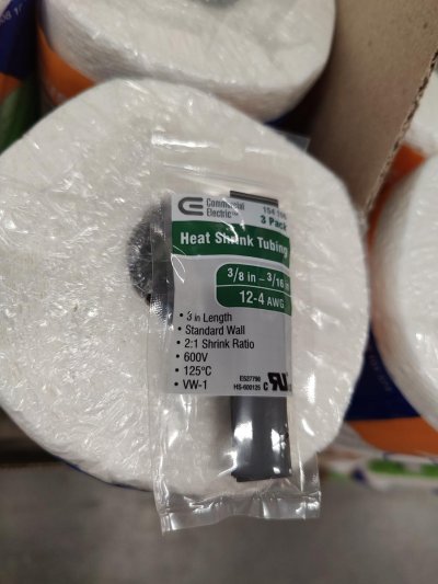
I only found heat shrink tubing with 2:1 shrink ratio. This size looks large enough to accommodate 3 wires.

Assuming a crimp connection at a DC terminal lug, you would enclose the connection with heat shrink, fill in hot glue then apply heat, right?


17070093147703417224361952226208.jpg

Use the connector that matches the size of the wire you are crimping it onto.

On my boat, for small wires I would use connectors that include heat-shrink plastic with hot glue inside to cover the crimp area. If those aren't available, or on battery-size cables, I would cover the crimp area and some of the wire with a separate piece of heat-shrink plastic tubing with hot glue inside. An inexpensive craft-oriented heat gun can do the job.
 
Thanks for showing the code

I would not challenge myself to pick up the new skill this time

Yes, your wallet will be lighter after the purchase.

In theory, the advertised benefits include not needing a crimp tool and a greater resistance to pull out.

The reality is that they are an expensive and possibly risky solution to problems that do not exist.

Soldering wires is generally not recommended in boats because, at the joint, it creates a solid conductor from a stranded one, making the interface very subject to vibration and movement cracks and resulting failure.

For this reason, last time I looked at the ABYC guidelines they read, "Solder shall not be the sole means of mechanical connection in any circuit. If soldered, the connection shall be so located or supported as to minimize flexing of the conductor where the solder changes the flexible conductor into a solid conductor." And "If one is incapable of soldering correctly, or incapable of adequately supporting the wire being connected to a soldered connection, it is recommended that they do not solder."

I don't know if it has been specifically addressed since last time I looked, but I suspect it isn't entirely clear when, or if, these connectors are ABYC compliant. Concerns might be that the adequacy of the support may depend up the length, fit, adhesion, and rigidity of the tubing, which may be variable, as well as the specifics of the installation, including, for example, the mechanical load imposed by the wires upon the joint.

They might also leave it to tradesmenship w.r.t. whether or not it is good enough in a particular installation. Some things are necessarily left to skill and judgement. I dont know.

In any case, it isnt necessarily clear to me that they are, or are not, ABYC compliant in any particular use. I'd be a lot more likely to use them for tiny thin wires for which good crimp solutions are hard to find and for which the tubing walls are very thick and rigid as compared to the wire vs for thick wires, where the load imposable by the wire may more easily dominate the rigidity and support of the relatively thin tubing wall and for which crimp connectors are readily available and highly reliable.

Also, the solder used in these connectors is lower temperature than normal solder. I don't know how it's properties otherwise differ.

In any case, for what you are doing, I'd likely save the money on the expensive connectors and buy a good crimper: You'll be far ahead in time and money and utility in the long run. I think.
 
You can remove the captive screws w/o much effort. If you can't do it with the screwdriver, a vice grip (needle nose) will finish the job easy.

And then just use some new (standard hardware store) screws and don't hassle the buggered threads.

And yeah, rings - :)
 
Greetings,
Re: Post #97. I would caution against replacing supplied hardware (screws) with anything else (standard hardware material). You might void UL certification. I think outlet screws are brass and replacing with plain steel would promote rust IMO.


I've never had any problems backing out the supplied captive screws and re-using BUT we're talking about a neophyte who MAY not have the experience to do so. NOT a bad thing but we don't know what we don't know when we're just starting out. I'm thinking a newbie may not recognize a cross threading situation, for example.
 
What's the purpose of the hot glue? Does a dielectric grease work equally well?

I only found heat shrink tubing with 2:1 shrink ratio. This size looks large enough to accommodate 3 wires.

Assuming a crimp connection at a DC terminal lug, you would enclose the connection with heat shrink, fill in hot glue then apply heat, right?


View attachment 145558

I’ve used that exact heat shrink before, it’s pretty good stuff. The glue is already included in the inside of the tubing. As you heat to shrink, the glue melts and the shrinking forces the glue into all the voids, and fastens the wires insulation to the heat shrink.
 
I’ve used that exact heat shrink before, it’s pretty good stuff. The glue is already included in the inside of the tubing. As you heat to shrink, the glue melts and the shrinking forces the glue into all the voids, and fastens the wires insulation to the heat shrink.

Thanks. the package does not mention adhesive lined, so I thought there is no adhesive

with a shrink ratio 2 to 1, the dia can shrink from 3/8" to 3/16"
but why is that compatible with wires b/t 12awg to 4 awg?

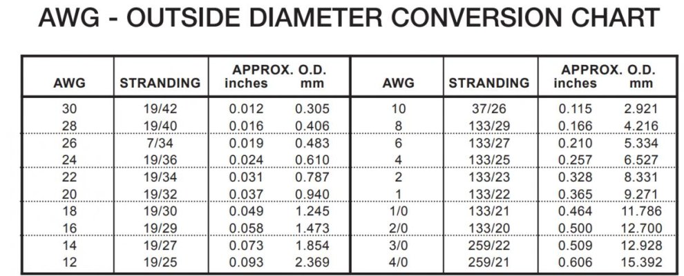
e.g. 10awg wire has a dia 0.115", this is smaller than 3/16" (0.1875")

Screenshot 2024-02-04 105840.jpg
 
Last edited:
You can chase the holes with a 8-32 or a 10-32 tap as well.

I use ring terminals and back out the screws.

If you use a hospital grade outlets (with the little green circle) the screws and terminals (usually) will be brass plated for hot and ground and nickel plated for line.

I backed out the hot screw from the LOAD to confirm the screw size. there is no other way to take the measure due to the recess in the plastic molding. it was fairly easy to put the screw back and the captive thread still seem to work. the LOAD in this outlet will not be used so it's not a concern.

I got the dia 0.1610 so it is #8

what do you mean to "chase the holes"?
 
If the heat shrink package doesn’t say “adhesive lined” then it doesn’t have the glue in it. That same company makes both kinds. Look for something rated for direct burial, that will have the lining you want. (Usually)
When someone says chase the holes, they mean to run a tap through it to make sure the threads are clean and proper.
Usually it’s referred to as chasing the threads.
 
what do you mean to "chase the holes"?

This means running a "tap" (male thread cutter) into the hole. This would clean up the female threads in the hole.

However, the female thread is not the issue. The anti-backout feature is at the tip of the male thread. Once you re-insert the screw past the difficult bit the screw goes loose again. So chasing the female thread is not productive.

If you want to eliminate the difficult bit, substitute an ordinary #8 screw for the special one. I use stainless screws. (the original screws are carbon steel with coloured plating)

Paulga - if you are following all this you must have the patience of Job !
 
I only have pinched downtime to work on this, so patience is all I can have

This means running a "tap" (male thread cutter) into the hole. This would clean up the female threads in the hole.

However, the female thread is not the issue. The anti-backout feature is at the tip of the male thread. Once you re-insert the screw past the difficult bit the screw goes loose again. So chasing the female thread is not productive.

If you want to eliminate the difficult bit, substitute an ordinary #8 screw for the special one. I use stainless screws. (the original screws are carbon steel with coloured plating)

Paulga - if you are following all this you must have the patience of Job !
 
Last edited:
If the heat shrink package doesn’t say “adhesive lined” then it doesn’t have the glue in it. That same company makes both kinds. Look for something rated for direct burial, that will have the lining you want. (Usually)
When someone says chase the holes, they mean to run a tap through it to make sure the threads are clean and proper.
Usually it’s referred to as chasing the threads.

Thanks. The adhesive is to be melted to create a moisture-resistant barrier, so it's important.

this Ancor 304602 should work for this purpose


p.s it just came to me that the "12-4awg" means that tubing accommodates 4 bare 12 awg wires, it does not mean it works for wires from 4 to 12 awg.

maybe in some applications, 4 wires are usually sealed together in a bundle

The ancor heat shrink is high quality, use with confidence.
12-4 is usually referring to bundled wire. Like SO or SOOW or similar. These have different insulating properties and different chemicals they’re resistant to. So, 4 each #12 single wires, will be slightly smaller as a group than 4-12 would be.
Many times it’s just not possible to answer all the questions as to what fits and what doesn’t without doing some test fitting and trial and error.
 
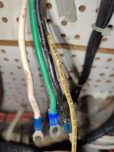
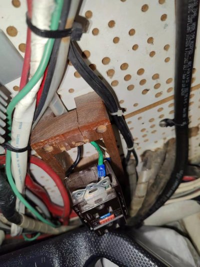
to further check the wire gauge directly connected to the outlet, I disconnected the 3 wires last night, but there are no markings along the jackets. The wires appear thicker than the home depot 12awg yellow wire, so are they likely also 12awg?

however, the terminals show "16-14" markings, does this suggest the wires are 14g?

Image_20240205084417.jpg

Image_20240205084409.jpg


Image_20240205084335.jpg
 
Good pictures, Paulga - mkes it much easier to help you!

The unmarked wires look fatter than 14 gage due to the comparison with the marked 12 gage (12AWG) wire and so are probably 12 gage.

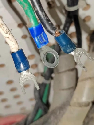
How did the installer manage to insert these wires into terminals which are sized for 14 to 16 AWG? (the 14-16 size is always coloured blue, by the way).

It may be that he/she/other cut off a some of the strands where the wire exits the insulation, so that the remaining strands would fit into the barrel of the terminal. This is not good practice, but does happen. Correct practice would have been to use the larger yellow terminals which are good for 10 gage to 12 gage.

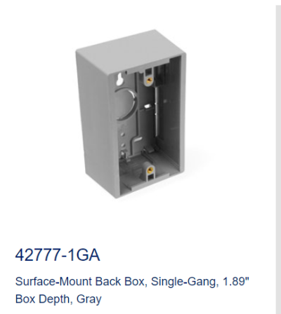
Changing subject, do yourself a great favour and install a proper box insted of the wooden mount. Here is a link to one such box:

https://www.leviton.com/en/products/42777-1ga
 

Attachments

  • elec box.png
    elec box.png
    44.5 KB · Views: 23
My guess is whomever terminated those crimps trimmed a few strands to get the 14-16
AWG terminals to fit. Probably a good idea to redo those anyway with new yellow ones for the larger gauge. That yellow one looks to be solid core, not sure what that goes to but not ideal.
 
My guess is whomever terminated those crimps trimmed a few strands to get the 14-16
AWG terminals to fit. Probably a good idea to redo those anyway with new yellow ones for the larger gauge. That yellow one looks to be solid core, not sure what that goes to but not ideal.

the yellow wire is stranded i think 19/25 but didn't count. It's a freebie from a home depot agent
 
yes, i already bought this

can yellow terminals work with 14g wire? just curious

Good pictures, Paulga - mkes it much easier to help you!

The unmarked wires look fatter than 14 gage due to the comparison with the marked 12 gage (12AWG) wire and so are probably 12 gage.

How did the installer manage to insert these wires into terminals which are sized for 14 to 16 AWG? (the 14-16 size is always coloured blue, by the way).

It may be that he/she/other cut off a some of the strands where the wire exits the insulation, so that the remaining strands would fit into the barrel of the terminal. This is not good practice, but does happen. Correct practice would have been to use the larger yellow terminals which are good for 10 gage to 12 gage.

Changing subject, do yourself a great favour and install a proper box insted of the wooden mount. Here is a link to one such box:

https://www.leviton.com/en/products/42777-1ga
 
yes, i already bought this

can yellow terminals work with 14g wire? just curious

Did you mean yellow terminals with 12g wire? yellow is for 12-10g.

Looking at photo. The black wire into blue terminal would only fit with several strands cut off. You should be able to verify wire strand ends.

You showed a 20A breaker for this plug, I suspect those wires could be 10g trimmed to 14g size. Or 12g with thicker skin than the sample 12g yellow wire.

Cut off the terminal, trim wire for a new terminal without cutting off any strands and you will see it does not fit into a new blue terminal.

Also the box may need to be relocated if the wires are too short after cutting off the terminals.
 
Understanding that this Engine Room routed circuit is supplied by 20 Amp breaker, you really need to confirm what is the gage of the wire and the wire's insulation (jacket) temperature rating. Both are normally written on the outer jacket that envelopes the 3 wires resulting in a flat cable. You can always measure the copper wire itself, but you cannot determine the temperature rating (usually between 60º C. & 200º C.). This temperature rating has a big part to play in the current carrying capacity (called Ampacity) of the wire.

It gets worse, the Ampacity is also effected by how many current carrying wires are bundled together along the route to the breaker. If we were to say there are 6 bundled together the Ampacity of 14 Gage wire with an insulation temperature rating of 60º C. has an Ampacity of just 7 Amps, if the insulation's temperature rating is 105º C. (common UL1426 boat cable) Ampacity is up by 240% to 17 Amps. Isn't life grand!

If all of the above condition stay the same except that there are only 2 wires bundled together (Green wires don't count) the respective values are 11 and 29 Amps.

I suspect that the existing wires are indeed 14 Gage, (outside insulation diameter is not a good indicator for gage as too many insulation types exist) and appear to be type 2 stranded (19 individual wires in the insulation) which is acceptable for general purpose wire aboard. I also suspect that the insulation's temperature rating is at best 75º C. as I don't recall ever seeing type 2 stranded wire with a higher rating unless the insulation is silicone based. Although there are lots of things that I've never seen.

The fact that the individual copper conductors are not tin plated has no role in the electrical performance of the wire, but does play a small role in it's survivability.

What to do? You really need to determine the wire size and temp.rating. Without that we are all guessing. Good luck digging the wire out.
 
Luna, you have to agree even when the boat was new a 20A breaker would not be used on 14g wire. So if the breaker is original the wire should be at least 12g.
 
Steve, why would I have to admit that?

According to ABYC (who I admit have some overly generous ampacity values compared to most other authorities) Two bundled, 14 Gauge conductors with 105º C insulation in the ER are capable of carrying 29 Amps each.

Route them outside the ER to the head and these same two are good for 35 Amps each.

Use wire with a silicone based 200º C rated insulation and the same two 14 gauge conductors are capable of carrying 45 Amps each, regardless of whether they are going to the ER or the head.

What matters is determining what is there now, not what someone else did.
 
the outer jacket is a spiral semi transparent band w/o any markings. it can be unraveled to expose the individual wires.

probably the gauge does not matter.

As the wires have little reserve in length, and it's not easy to change the location of the electrical box, I intend to reuse the existing terminals as is.

Is there no problem adding a 12g grounding wire b/t the box and the gfci grounding terminal, no matter the wires are 10/12/14 g?


Understanding that this Engine Room routed circuit is supplied by 20 Amp breaker, you really need to confirm what is the gage of the wire and the wire's insulation (jacket) temperature rating. Both are normally written on the outer jacket that envelopes the 3 wires resulting in a flat cable. You can always measure the copper wire itself, but you cannot determine the temperature rating (usually between 60º C. & 200º C.). This temperature rating has a big part to play in the current carrying capacity (called Ampacity) of the wire.

It gets worse, the Ampacity is also effected by how many current carrying wires are bundled together along the route to the breaker. If we were to say there are 6 bundled together the Ampacity of 14 Gage wire with an insulation temperature rating of 60º C. has an Ampacity of just 7 Amps, if the insulation's temperature rating is 105º C. (common UL1426 boat cable) Ampacity is up by 240% to 17 Amps. Isn't life grand!

If all of the above condition stay the same except that there are only 2 wires bundled together (Green wires don't count) the respective values are 11 and 29 Amps.

I suspect that the existing wires are indeed 14 Gage, (outside insulation diameter is not a good indicator for gage as too many insulation types exist) and appear to be type 2 stranded (19 individual wires in the insulation) which is acceptable for general purpose wire aboard. I also suspect that the insulation's temperature rating is at best 75º C. as I don't recall ever seeing type 2 stranded wire with a higher rating unless the insulation is silicone based. Although there are lots of things that I've never seen.

The fact that the individual copper conductors are not tin plated has no role in the electrical performance of the wire, but does play a small role in it's survivability.

What to do? You really need to determine the wire size and temp.rating. Without that we are all guessing. Good luck digging the wire out.
 
I didn't mean to ask for confirmation if yellow terminal is 10-12g, I want to know if it works with 14g wires


Did you mean yellow terminals with 12g wire? yellow is for 12-10g.

Looking at photo. The black wire into blue terminal would only fit with several strands cut off. You should be able to verify wire strand ends.

You showed a 20A breaker for this plug, I suspect those wires could be 10g trimmed to 14g size. Or 12g with thicker skin than the sample 12g yellow wire.

Cut off the terminal, trim wire for a new terminal without cutting off any strands and you will see it does not fit into a new blue terminal.

Also the box may need to be relocated if the wires are too short after cutting off the terminals.
 
the outer jacket is a spiral semi transparent band w/o any markings. it can be unraveled to expose the individual wires.

probably the gauge does not matter.

As the wires have little reserve in length, and it's not easy to change the location of the electrical box, I intend to reuse the existing terminals as is.

Is there no problem adding a 12g grounding wire b/t the box and the gfci grounding terminal, no matter the wires are 10/12/14 g?

Yes, there is spiral loom on the visible wires. It could be such that inside the wall and along the rest of the wire's route, there exists the factory outer jacket that groups these 3 wires together. This type of outer jacketed wire is commonly used as it speeds up installation.

The individual wire's size and temp rating should be marked on this outer jacket and/or the individual wires. You just need to find the markings!

Without a doubt, the gauge and temp. rating matter!

Inside the metal box, the new grounding wire from box to the GFCI should be the size of the supply conductors, although if this was a terrestrial based installation the wire can be one size smaller and even uninsulated.
I don't know if ABYC allows those two things, as it's just easier to use the same green wire.
 
I didn't mean to ask for confirmation if yellow terminal is 10-12g, I want to know if it works with 14g wires

My opinion:

To answer your question - It is not good practice. You will have higher risk of a poor connection. You may have to resort to this when at sea to achieve a fix, but should never do this on land.

If you do crimp a yellow terminal onto a 14awg wire you should apply lots of crimping force and then really pull hard on the wire - trying to pull it out of the terminal - to ensure that the terminal is really holding the wire.

Another trick is to fold the wire strands double before inserting into the terminal.
 
Back
Top Bottom