Parallel 12V Batts

The friendliest place on the web for anyone who enjoys boating.
If you have answers, please help by responding to the unanswered posts.

DonW28

Senior Member
Joined
Dec 3, 2019
Messages
135
Location
USA
Vessel Make
2006 Mainship 34T
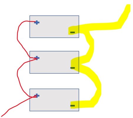
Maybe I'm trying to simplify something that is more complicated than I'm seeing but here goes. When I look at diagrams on how to parallel 2 12V batts they all seem to show the source taking the power (starter, thruster, etc.) hooked with the positive to the positive of one of the two and the negative to the negative of the 2d battery and then you connect pos. of bat one to pos of bat. 2 and same with negative. Why? Seems much easier to just run the positive and negative off the starter or thruster to the first battery and then "jump" to the 2d with your connector wires like a mini-jumper cable about 1 foot long.


I have to be missing something since jumper cables obviously parallel batteries temporarily and a 1 foot long one permanently connected set seems easier than using a positive off one battery and negative off the other.


Don
 
You want to hook the positive to positive and the negative to negative. Then take the positive off one battery to the engine and the negative off the other battery to the engine. If you take both positive and negative off one battery the second battery will not contribute much if anything due to the resistance in the cables. In a bank you always want to take positive off one end and the negative off the other end.
 
You want to hook the positive to positive and the negative to negative. Then take the positive off one battery to the engine and the negative off the other battery to the engine. If you take both positive and negative off one battery the second battery will not contribute much if anything due to the resistance in the cables. In a bank you always want to take positive off one end and the negative off the other end.


I figured there was a reason I wasn't seeing. Raining today in Key West so I'm bored and asking boat questions. Thank you for the response.


Don
 
Another quick question. What about the battery charger? Do you hook + to one battery and - to the other like the engine?


Thanks, Don
 
Last electrical question for the day. Say the run to the starter is 4/0 wire. But the 2 batteries are sitting right next to each other. Run if maybe 12-18 inches at the most to allow for bending the wire. Do you still have to go 4/0 or can you step it down given the very short run?


Thanks,


Don
 
Anytime you run wire the bigger the better within reason. Keep it 4/0.
 
Agree that bigger is better but IMO importance is for larger on longer runs (lowers V drop) and next having all jumpers same length and wire gauge (balanced load & charging on battys).
I believe it's pretty common to use say 2/0 for jumpers even where long runs are 4/0. Actually that's my plan when I replace 2 - 8Ds with 4 - GP 31's


This post has gotten me a bit more inclined to learn about batteries although I never intend to live on the hook without a generator. I found, and regretfully did not bookmark, a really good site about how to size the jumper wires on banks based on the maximum amp draw. While I don't recall the specifics the author showed how you could seriously reduce the size of the jumper wires based on variables like the longest run on the system and the number of batteries (AH) in the bank. I recall one example where you could safely go 1/6th the size of the run off the bank for the jumpers. Again, I'm so far from smart about this it is scary. But so far most of what I'm learning is starting to make sense to me. I should have book marked the page.


Guess if you use a 2/0 jumper for a 4/0 run unless you have a really short run or like to kept your batteries well spaced for some reason you should be perfectly safe.


Don
 
Don
I agree especially with 12V in parallel as each contributes half the A.
With 6V in series it carries the full amps.
 
This post has gotten me a bit more inclined to learn about batteries although I never intend to live on the hook without a generator. I found, and regretfully did not bookmark, a really good site about how to size the jumper wires on banks based on the maximum amp draw. While I don't recall the specifics the author showed how you could seriously reduce the size of the jumper wires based on variables like the longest run on the system and the number of batteries (AH) in the bank. I recall one example where you could safely go 1/6th the size of the run off the bank for the jumpers. Again, I'm so far from smart about this it is scary. But so far most of what I'm learning is starting to make sense to me. I should have book marked the page.


Guess if you use a 2/0 jumper for a 4/0 run unless you have a really short run or like to kept your batteries well spaced for some reason you should be perfectly safe.


Don

It would be good to pick up a copy of Nigel Calder’s book “Boatowners Mechanical and Electrical Manual”. Great read.
 
Here is another one.
SmartGauge Electronics - Interconnecting multiple batteries to form one larger bank


I have 3 x 12V batteries and use the #3 dwg.

I made the + leads all the same length and from the same spool of wire.
I made the - leads all the same length and from the same spool of wire.

Note though that the + & - are not necessarily the same length as the other polarity.

I stacked the + leads on the buss #1, #2 , #3.

It won't matter if the order on each buss is reversed as long as they are reversed.

I then reversed the stacking on the - buss, #3. #2, #1

JMO
 
Yes for charging too. Maybe this article will clear it up.
View attachment 126302

This spring I am going to covert to lithium. In balancing, the dealer gave me the same PDF. But there is nothing on a 3 battery setup that I want to do.

Other than connecting all three batteries to a buss bar and than connect the main cables to the bar. I more complicated install, rather than jumping from battery to battery. But this method can be used for any amount of batteries. But you must keep the all cables from battery to bass bar the same size and length. Oh well, more cable. :D
 
This spring I am going to covert to lithium. In balancing, the dealer gave me the same PDF. But there is nothing on a 3 battery setup that I want to do.


Other than connecting all three batteries to a buss bar and than connect the main cables to the bar. I more complicated install, rather than jumping from battery to battery. But this method can be used for any amount of batteries. But you must keep the all cables from battery to bass bar the same size and length. Oh well, more cable. :D
I disagree that buss bar is only option with three in parallel... its a good one but not only one

Line up 3 and attach main + & - cables to opposite end batty and jumpers to the other two. If same Lgth & cable size all battys see a main cable plus 2 jumpers in any charging or draw circuit... Basically the same principle as 2 or 4 in parallel.
It doesn't matter whether the cable resistance is on the + or - side of the circuit to reach balance.
 
This spring I am going to covert to lithium. In balancing, the dealer gave me the same PDF. But there is nothing on a 3 battery setup that I want to do.

Other than connecting all three batteries to a buss bar and than connect the main cables to the bar. I more complicated install, rather than jumping from battery to battery. But this method can be used for any amount of batteries. But you must keep the all cables from battery to bass bar the same size and length. Oh well, more cable. :D

I put lithium batteries in our last boat. I put in 3 and made copper bus bars to hook them together. I think it was easier to do compared to cables and it was certainly a cleaner install. The bus bars locked the batteries in place and they were rock solid. I used shrink tube to insulate the bus bars between the batteries. Just measure carefully when you are drilling the bus bar so they line up correctly. The batteries I used had removable posts so I had a solid horizontal surface to bolt the bus bars to. I looked but I guess I didn’t keep any of the photos of them.
 
I disagree that buss bar is only option with three in parallel... its a good one but not only one

Line up 3 and attach main + & - cables to opposite end batty and jumpers to the other two. If same Lgth & cable size all battys see a main cable plus 2 jumpers in any charging or draw circuit... Basically the same principle as 2 or 4 in parallel.
It doesn't matter whether the cable resistance is on the + or - side of the circuit to reach balance.

I am not understanding how you are wiring them?:banghead:
 
I am not understanding how you are wiring them?:banghead:

Iggy
Picworth 1,000 words see if this helps?

Each Circuit path is 2 main cables plus 2 jumpers
 

Attachments

  • 3 Batty Balanced.jpg
    3 Batty Balanced.jpg
    30.1 KB · Views: 17
Great thread....just ordered my book looks like a awesome book.
 
Iggy
Picworth 1,000 words see if this helps?

Each Circuit path is 2 main cables plus 2 jumpers

Now if you look at the top of page 3 of your PDF. It shows that the middle batteries will pull less that the outer two. Its the same wiring but one less battery. In there words, "However, this method of wiring is still not perfectly balanced."

I am no expert on Lithium! But spending 5K on batteries and the rest of the needed parts I want to do it right. Not very sure if there is a real difference between your way/Method One and using a cables from each battery to a buss bar.

I guess my point is, I don't want to have any problems years later. Lithium is not your normal battery and very new for us to work with. Thank you for your input!
 
Now if you look at the top of page 3 of your PDF. It shows that the middle batteries will pull less that the outer two. Its the same wiring but one less battery. In there words, "However, this method of wiring is still not perfectly balanced."


I am no expert on Lithium! But spending 5K on batteries and the rest of the needed parts I want to do it right. Not very sure if there is a real difference between your way/Method One and using a cables from each battery to a buss bar.


I guess my point is, I don't want to have any problems years later. Lithium is not your normal battery and very new for us to work with. Thank you for your input!
I think you are referring to the attachment in post #16. Not my post but I agree with it. I think you are comparing their method #2 to my dwg above but I dont think that's a fair comparison.
If you count the # of jumpers each batty curcuit sees in #2 they are not equal. The dwg I posted has the same # of jumpers for all 3 battys... same #, same Lgth = same resistance and equal draw & charge.
If you look at method #4 it shows the same principle with 4 battys. Where they count # of jumpers except in that case they are mixed some long some short but all have same # of each so same resistance therefore balanced

Nothing wrong with #3 and it is also perfectly balanced.

MY FAULT!!! I meant Method 1 NOT #2. Sorry about that. I was seeing 3 pics of how batteries were wired and counting them.

Now there is no #4, think you did the same thing.

Now if I am reading your post right "I posted has the same # of jumpers for all 3 battys... same #, same Lgth = same resistance and equal draw & charge."

Its not the same resistance. Methord 1 shows that since both end batteries are using less cables. An Omh meter would read zero, but under load and the greater the load the more resistance will be produced within the cables.

But with lithium, as small as this may be I am not sure if it matters. With AGMs I would not hesitate to wire them up that way!
 
Last edited:
Iggy
Maybe we are looking at different PDFs so I'll try to clarify my point.
I don't think it matters to you as you have already decided what you will do -
I'll try to be clear for others use, info etc.

MY FAULT!!! I meant Method 1 NOT #2. Sorry about that. I was seeing 3 pics of how batteries were wired and counting them.

Now there is no #4, think you did the same thing.

Now if I am reading your post right "I posted has the same # of jumpers for all 3 battys... same #, same Lgth = same resistance and equal draw & charge."

Its not the same resistance. Methord 1 shows that since both end batteries are using less cables. An Omh meter would read zero, but under load and the greater the load the more resistance will be produced within the cables.

But with lithium, as small as this may be I am not sure if it matters. With AGMs I would not hesitate to wire them up that way!

Method 1 is clearly not balanced and can create some issues long term

Method 2 is a sight improvement over Method 1 but shows the imbalance - If you follow each batty circuit (from main - cable through jumpers to main + cable) you will see that different battys have a different # of jumpers and therefore different length & different resistance

My suggested Dwg for 3 battys - all 3 battys have the same # of jumpers (2) from main - cable to main + cable. Same # jumpers - same length = same resistance. Should be as balanced as Method 3

Batty Bal Method 3 - Perfectly Balanced Totally agree - may be more involved for some installations though
In fact if you look carefully the buss bar method has 2 jumpers per batty - 1 Pos 1 Neg from the buss bars... same as my diagram.


Batty Bal Method 4 - if you note this is also perfectly balanced as the jumper # and length (and resistance) is equal even though their are 2 different jumper lengths in each batty circuit.

This is the principle I applied to my diagram and explanation of why that arrangement for 3 battys is equal to the buss bar method - no better but equally as balanced. in fact if you look carefully the buss bar method has 2 jumpers per batty - 1 Pos 1 Neg from the buss bars.
 

Attachments

  • Batty Bal Method 1.jpg
    Batty Bal Method 1.jpg
    134.2 KB · Views: 21
  • Batty Bal Method 2.jpg
    Batty Bal Method 2.jpg
    105.7 KB · Views: 16
  • 3 Batty Balanced.jpg
    3 Batty Balanced.jpg
    30.1 KB · Views: 17
  • Battyy Bal Method 3.jpg
    Battyy Bal Method 3.jpg
    88.8 KB · Views: 18
I am so sorry!! But to me your diagram is no different than Method 2 except one less battery. The only other way using your diagram and I could be wrong. Is to add a jumper from the POS side of the #1 to the third battery and the same to the Neg side.

This would add LESS resistance between the two end batteries. But something tells me I am wrong in this as to balancing.
 
I am so sorry!! But to me your diagram is no different than Method 2 except one less battery.

I'm done.... count the number of jumpers! Why is that so hard? It is VERY DIFFERENT. The diagram may look similar but it is NOT the same situation... If you can count.
I understand your mind is made up and closed to reason.
Your scheme is perfectly balanced so no issues what so ever.

My post is for others info.
 
Last edited:
I can’t dig into it now, but it’s more complicated than just the number of jumpers. I have a degree in electrical engineering, and it didn’t dawn on me until recently how complicated this really is.

One thing to keep in mind is that the current flowing thought each jumper diminishes with each jumper, and with it the voltage drop changes, and with it the current flow changes.

If possible, equal length cables from each parallel bank to a big fat bus bar I think is the best approach.

Twistedtree
Admit I'm not a EE but am a ME and go by what my research tells me.
What is your take on the following which is method 4 from that linked article? It specifically cites the # of jumpers and even uses some long some short but makes the point that all battys see the same # of each.

Also what is your take on a 2 parallel batty bank with Pos and Neg cables attached to different battys and Pos to Pos jumper and Neg to Neg jumper...
is that balanced or not? In addition to the main cables Each batty sees one jumper in the circuit... they are on opposite sides of the circuit one Neg and one on Pos. I tried to draw a diagram but messed up somewhere. its similar to my 3 batty bank diagram above with the center batty removed. Balanced or not?
 

Attachments

  • Batty Bal Method 4.jpg
    Batty Bal Method 4.jpg
    58.4 KB · Views: 16
Twistedtree
Admit I'm not a EE but am a ME and go by what my research tells me.
What is your take on the following which is method 4 from that linked article? It specifically cites the # of jumpers and even uses some long some short but makes the point that all battys see the same # of each.

Also what is your take on a 2 parallel batty bank with Pos and Neg cables attached to different battys and Pos to Pos jumper and Neg to Neg jumper...
is that balanced or not? In addition to the main cables Each batty sees one jumper in the circuit... they are on opposite sides of the circuit one Neg and one on Pos. I tried to draw a diagram but messed up somewhere. its similar to my 3 batty bank diagram above with the center batty removed. Balanced or not?


The two bank config I think is simple enough to say it's balanced.


Beyond that, the honest answer is that I don't know. What I've learned is that a cursory inspection and counting the number of jumpers doesn't necessarily tell the whole story. So the "intuitive" answer may not be right. As you surely know, this is all too often the case in engineering. Also, to be brutally honest, I'm pretty rusty with this stuff after 40 years, so am not the best person to really analyze it. I just know enough to know when to keep asking questions because it doesn't all add up. There are a few other forums with people who are much more practiced in this than I am, and maybe then can be tempted into participating. I switched pretty early from EE to computers, so never really practiced EE other than to know when to drill down on guys in my team who maybe weren't on top of things.


But just looking at the diagram of batteries, and putting together a circuit that models it, my head starts to ache. And the author of those diagrams says as much regarding the difficulty of really modeling it. Batteries aren't pure current sources, nor pure voltage sources, nor a fixed resistance. You could (I would) probably make a simplifying assumption and model it that way, then do the same a few more times with a few different simplifying assumptions to try to bracket the answer, or at least gain a better understanding of the moving parts.


Part of the attraction of the bus bar approach is that it's more understandable since each parallel bank can be made electrically identical. Even if the battery's behavior is variable, it will vary the same across each bank. So the behavior of each bank is somewhat unknown, yet know to be equal to the other banks. Equal but unknown - there's a concept to ponder.
 
Back
Top Bottom