LITHIUM HOUSE AGM STARTERS

The friendliest place on the web for anyone who enjoys boating.
If you have answers, please help by responding to the unanswered posts.

seadog52

Member
Joined
Apr 12, 2024
Messages
6
Location
new jersey
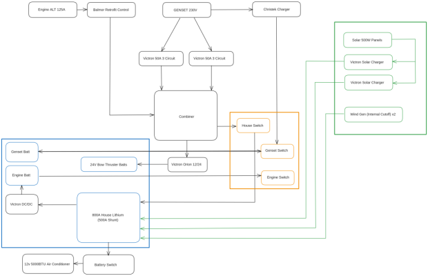
looking to change my house bank to 800amp lithium, but keep my starters as agm. I have attached a proposed flow diagram , my main concern is the alternator ability, i assume the dc/dc to the engine start is correct? should the wind gens be on a dc/dc? The reason for the large house is for a future 5000btu 12 volt ac unit. Thanks for any input
 

Attachments

  • boat_diagram (1).png
    boat_diagram (1).png
    65.7 KB · Views: 107
I hope you mean LifePO4 batteries. Protecting your alternator and LifePO4 batteries is the priority in your system. I'm starting a similar system on my boat, so I'm still trying to figure this out too. My problem is my 12 volt alternator charging my 24 volt house bank. Look at the Wake speed WS500 to protect your alternator. There are also components to protect LifePO4 batteries from alternator spikes as well. I would also add breakers between the solar panels and the Victron MPPT controllers. Looking forward to seeing your completed system.
 
I hope you mean LifePO4 batteries. Protecting your alternator and LifePO4 batteries is the priority in your system. I'm starting a similar system on my boat, so I'm still trying to figure this out too. My problem is my 12 volt alternator charging my 24 volt house bank. Look at the Wake speed WS500 to protect your alternator. There are also components to protect LifePO4 batteries from alternator spikes as well. I would also add breakers between the solar panels and the Victron MPPT controllers. Looking forward to seeing your completed system.
Yes so far SOK 206 amphr marine batts seem the best , you can even replace bms and individual cells. And yes its my alternator im worried about i will check out the ws500. For you check out the victron Orion 12/24 charger i use that for my 24v bow thruster batt works great
 
what is a Balmor retrofit control? If it is a regulator than can be programmed to charge LFP LifeP04 batteries then your schematic will work.
 
You may want to look at the Epoch batteries. They seem to have moved ahead of SOK for controls and monitoring. Much depends on form factor for available space though.

A couple tips. Im not a "brand Nazi," but will not use anything but Blue Sea for electrical components such as bus bars and circuit protection. You can find similarly speced Chinese stuff for less than half the cost, but it's false savings.

Sounds like you're headed towards four batteries (4 x 206 = 800 Ah). Suggest hub and spoke config of batteries to bus bar vs daisy chain.

One item to highlight is to make sure your cabling from alternator to LFP bank is oversized - both negative and positive cable runs (especially negative since your regulator will not compensate for undersized - learned the hard way).

Finally, your alternator will be working extra hard. Make sure the mounting brackets are up to the task. Stock brackets on yy small Perkins 75hp are a bit puny.

Peter
 
I have the same set up on my boat. Housebank is LiFePO4 and the starter plus thruster batteries are AGM.

The way it is set up is that I have 2 alternators on each engine. One is 12 V and charges the AGM batteries. The other alternators are 24 V and they charge the Lithiums. Those two alternators have Wakespeed WS 500 controllers and so far it works great.
When on anchor the solar panels will charge the housebank and if I would need the generator then the inverter can charge the housebank as well. Same goes if I would be on shore power, also then the inverter will charge the house bank.
I also have a 220 to12 V 25 A charger which is connected to the inverter output and to the 12 V AGM batteries. After all, sometimes you come into a port, have to use the anchor or the thrusters, but then you shut the engines down. In that case the batteries would not get charged anymore, so for that circumstance I have the charger.
 
Do the OP’s engines meet the model and serial number requirements to have a Valeo alternator to work with the Balmar regulators. Those are fairly new, low hp, sailboat engines.

David
 
Last edited:
You may want to look at the Epoch batteries. They seem to have moved ahead of SOK for controls and monitoring. Much depends on form factor for available space though.

A couple tips. Im not a "brand Nazi," but will not use anything but Blue Sea for electrical components such as bus bars and circuit protection. You can find similarly speced Chinese stuff for less than half the cost, but it's false savings.

Sounds like you're headed towards four batteries (4 x 206 = 800 Ah). Suggest hub and spoke config of batteries to bus bar vs daisy chain.

One item to highlight is to make sure your cabling from alternator to LFP bank is oversized - both negative and positive cable runs (especially negative since your regulator will not compensate for undersized - learned the hard way).

Finally, your alternator will be working extra hard. Make sure the mounting brackets are up to the task. Stock brackets on yy small Perkins 75hp are a bit puny.

Peter
Thanks Peter, yes plan on doing the batts to bus bar, Sok is a size issue to fit x4, good tip on the cables will look at that. My biggest worry is the alternator!
 
Do the OP’s engines meet the model and serial number requirements to have a Valeo alternator to work with the Balmar regulators. Those are fairly new, low hp, sailboat engines.

David
Yes David, it is a sailboat ..you got me, but i have always found you trawler guys are really knowledgeable at this kind of stuff, i have always said its best to speak with people smarter then me!!
 
Hey, many of us were sailors before we became trawlerers, so ask away.

David
 
Sure i will be joining you at some point..(my wife would be there now!!) .if you have any input on my layout would appreciate it. My big concern is damage to the alternator, will probably increase wire gauge but what if battery bms cuts off with alternator still going? Will a regulator see that? Should i put the alternator thru a dc/dc charger instead?

thanks
 
You have identified one of at least two problems with an engine alternator charging a big bank of Li batteries.

When the BMS suddenly shuts off, it can cause a voltage spike at the alternator output and blow its diodes. Balmar makes a device that protects the alternator from this. Costs less than $100.

The other problem is overheating the alternator. If you attempt to recharge a depleted Li bank with the engine alternator it will pull maximum current and overheat. Balmar makes a temperature probe that attaches to one of the alternators case bolts and sends a case temperature signal to the regulator. At 200-225 deg F it starts cutting back current to keep the alternator from overheating.

Same cost as the diode protector above. Well worth installing.

David
 
David M is correct and brings up some salient points. When depleted, LifePo4 batteries will take everything the alternator can provide and cause the alternator to overheat. In my install I used a Balmar regulator using the 'Belt Manager' feature to limit maximum current to the batteries. (The Victron DC-DC charger could also perform this function). Since the start battery is also in circuit then, theoretically any BMS shutdowns should not cause a problems since the alternator output would not be open-circuit.
 
We have a similar approach as you have diagrammed. We use a Balmar Alternator Protect on each alternator. We have 3 Victron 30 amp dc/dc chargers that draw from the 800 AH LFP house bank and charge the start batteries and thruster/windlass batteries. Our 2000 W Magnum inverter/charger charging the house bank. We also have a Magnum trickle charger to charge the gen battery. We have solar panels that charge the house bank thru a Victron MPPT charge controller. We used 4 Discover Blue 200 AH batteries (L16 form factor) all wired with equal length to positive and negative buss bars. We have Balmar MC614 external regulators on 140 amp OEM alternators with internal regulators removed. They are programmed to limit their output and each alternator has a temp sensor that can limit output. The system works pretty well. The dual engine/alternator control is a work in progress but that’s another story won’t effect you.
 
We have 600amp of Battleborn for the last 2 years, love them. We use Balmar Charge Controller and Balmar Alternator Protector. I have Dc to DC setup in RV and do not care for it as much as Balmar setup. Both work, Balmar is cleaner install. I can tell you with out doing something you burn out your alternator as most are not design to put full ratting for hours at time. (we burned out one already prior to installing the Balmar. Breakers for to Turn off Solar panels to MPPT and After a what we did on the solar side of things. Your inverter charger is best friends as higher charging rate will really top off the LFP quickest.
 
Make sure that the AC you are getting has a 'soft start'. This is something that is necessary for the AC startup on batts so a gradual pull is put on the batts.

Also, with 2 dissimilar chemistries you might need more parts, it isn't just a dc/dc charge. Lithium requires special charging that the AGM will not support. Then you throw in a wind turbine.

I'd strongly suggest that you talk to people who have done this work while standing at the boat and then maybe hire that someone to help. None of us here really know what you have in your boat.

BoatUS says most boat fires are caused by electrical issues. Don't be someone who has this problem.
 
DC/DC Charger between your Engine Start battery and Lithium Batteries will limit load on alternator to rating of DC/DC Charger.
See attachment of system I installed on a twin engined trawler with 800ah Lithium Batteries.
 

Attachments

  • DC Charging.jpg
    DC Charging.jpg
    76.3 KB · Views: 30
So far this set up has worked for me for the past 2 years. But there is more ways to do this! The first thing I did was to add a heat sensor to the 120A alt. If it get s too hot the Reg will back it off. Than I removed the ARC that was charging both the Starting and house bank. The House bank was being charged first from the Charger/inverter and the ALT. I moved the sense and Alt wires from the House to the stating bank. Then installed two 30A DC2DC chargers to the house. Than added a 30A A.C. charger to the starting bank. ALL chargers are now set to for LI or AGMs. I kept the wiring to combine both banks in a starting emergency.

At the time of install, the ABYC standards where being set and it was mentioned that a 2nd source if the BMS went into shut down. So I took the house bank switch and the parallel switch and made them a solenoid type with the remotes at the helm. If the BMS cuts out, the House bank can be turned off and run the boat off the starting bank which can be done in seconds. Both of my switches are in the engine compartment.

This year I installed a bigger bow thruster and went with 24V. So now I added a 10A DC2DC charger between the starting and thruster bank. So now that puts a 20A load on the 120A ALT.

All max loads from the DC2DC chargers is now 80A plus the starting bank. To take some load off the ALT I have the DC2DC chargers turn on 3 minutes after the engine starts. This will give the staring bank a little time to charge back up.
 
Last edited:
So far this set up has worked for me for the past 2 years. But there is more ways to do this! The first thing I did was to add a heat sensor to the 120A alt. If it get s too hot the Reg will back it off. Than I removed the ARC that was charging both the Starting and house bank. The House bank was being charged first from the Charger/inverter and the ALT. I moved the sense and Alt wires from the House to the stating bank. Then installed two 30A DC2DC chargers to the house. Than added a 30A A.C. charger to the starting bank. ALL chargers are now set to for LI or AGMs. I kept the wiring to combine both banks in a starting emergency.

At the time of install, the ABYC standards where being set and it was mentioned that a 2nd source if the BMS went into shut down. So I took the house bank switch and the parallel switch and made them a solenoid type with the remotes at the helm. If the BMS cuts out, the House bank can be turned off and run the boat off the starting bank which can be done in seconds. Both of my switches are in the engine compartment.

This year I installed a bigger bow thruster and went with 24V. So now I added a 10A DC2DC charger between the starting and thruster bank. So now that puts a 20A load on the 120A ALT.

All max loads from the DC2DC chargers is now 80A plus the starting bank. To take some load off the ALT I have the DC2DC chargers turn on 3 minutes after the engine starts. This will give the staring bank a little time to charge back up.
@Iggy Not saying you are wrong BTW just curious to understand.
Why did you decide to remove the ACR and replace with a 3 minute delay timer to control DC2DC? I thought ACR would auto connect when charge voltage is reached.
With a 120A ALT & external regulator? with heat sensor, why did you change from direct charging the house through ALT set for LFP and then DC2DC to start & thruster. My thought is the ALT would charge house faster connected direct and then send surplus to DC2DC

The Timer is built into the Victron DC2DC charger which is set to Li. So no big deal there!

Why change the ALT if it is working? In my case, I can not set the ALT to Li. without replacing it. So its charging the AGM starting bank. Keep in mind, if the BMS did cut out. The ALT would be protected since its connected to the starting bank. To be on the safe side I have a 2nd source to power the house with the remote battery switches.

The ARC would or could damage the House bank since the ALT is set to AGM. Remember what the ARC does, it only parallels the 2 banks, no isolation. Pulse the DC2DC charger limits the current as not to burn the ALT up. The DC2DC charger is set to Li charging profile. Yes, the temp sensor can limit the current too.

To me, it was the easiest, safest and cheapest way to do this. At the time, it was meeting the ABYC standards.
 
OK. The timer is built in, not add on. I was thinking of using the ACR to trigger the DC2DC only. Your ALT, well I thought it was a programable regulator like discussed often here.
 
My ALT is a Balmar with a programable and external regulator. It can be set to flooded, gel, or AGM profiles. Along with other setting.

I should have said "without replacing the regulator" rather than the ALT. But I did not want the ALT charging the house bank for safety reasons.

For some boaters, they my want more amps to charge the house. When I bought the boat, it came with a 6k NL genset and a 3000W charger/inverter. On a day trip, I leave the slip with the batteries fully charged. In running we use about 25 to 30A. So no problems there.

On longer trips, I just use the genset to make coffee, hot water and charge the batteries. So far for 30 mins each morning and evening. The charger puts out about 100 amps.
 
Last edited:
Yes we all have our own needs and as long as those needs are managed it is all good.
But I did not want the ALT charging the house bank for safety reasons.
Please explain what safety reasons you are concerned about.
 
My ALT is a Balmar with a programable and external regulator. It can be set to flooded, gel, or AGM profiles. Along with other setting.

I should have said "without replacing the regulator" rather than the ALT. But I did not want the ALT charging the house bank for safety reasons.

Yes we all have our own needs and as long as those needs are managed it is all good.
But I did not want the ALT charging the house bank for safety reasons.
Please explain what safety reasons you are concerned about.
As mentioned, If the BMS disconnects the Alt will burn up. Or you must add a protection device and that device is not 100% fool proof.

Plus, ABYC was proposing a 2nd source if the BMS did disconnect. Please re-read my past post.

"The warning is more for a long term voltage fault. I.e. if the alternator’s own regulator fails for normal reasons and the alternators voltage rises the LED will simply warn of the high voltage at the alternator, this device cannot actually stop the high voltage occurring."

The above is from Sterling. Thats not to say I could be misunderstanding something.
 
As I said, your setup is not in dispute, sorry but safety to me means something different, I would have said protect the ALT from BMS shutdown.
 
I never said my setup was in dispute. I am not understanding why your asking the questions that you do. Also playing with my words. I now find it rude.

Oh well....................
 

Latest posts

Back
Top Bottom