dual shore power wiring

The friendliest place on the web for anyone who enjoys boating.
If you have answers, please help by responding to the unanswered posts.

sndog

Senior Member
Joined
Nov 15, 2022
Messages
206
Hello again everyone.

I am working on the electrical design for my refit. I have a question, I am looking at using 50A plugs, this is due to docks having 100A service fewer in between, and the cost of connectors and cabling, and handling the cable, seems to increase exponentially, rather than linearly.

I have 50A connectors and wiring on each side of my boat. My questions are running into the main electrical panels.

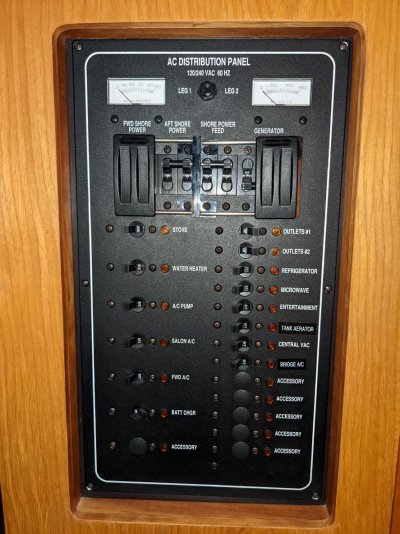
Currently, there are no electrical panels, I removed them and went from scratch.

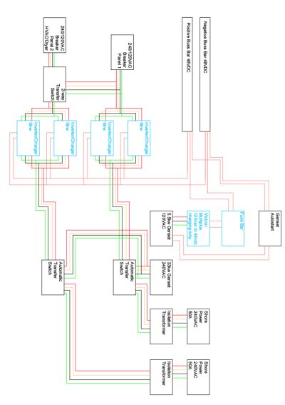
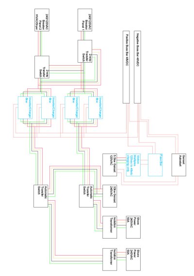
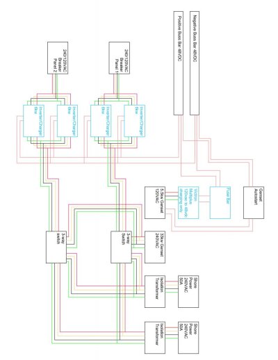
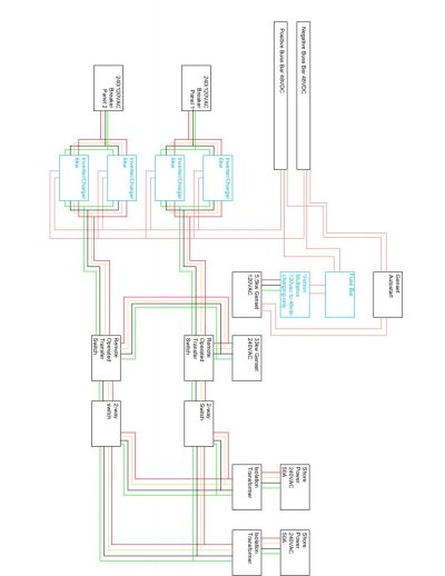
I have 24kw of inverter/charger input and a 33kw/240v genset.

How would I handle the wiring of breakers off of this without causing issues?

The genset and inverter charger can all run through a single transfer switch. If it was 100A shore power, it could run through a single 3-way transfer switch.

Power distribution to the breakers that need the different inputs is easily done, as I plan to convert AC units to one shore power and the rest to the other shore power.

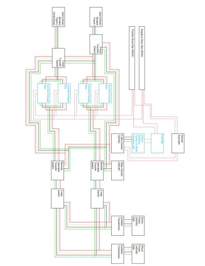
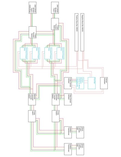
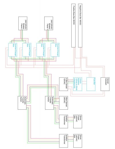
The picture attached is my idea of how to do it. Any thoughts, inputs, etc would be greatly appreciated as I need to start ordering the electrical gear in the next week or so.

Thank you as always
 

Attachments

  • Me Too Electrical input 05.12.23 Condensed.jpg
    Me Too Electrical input 05.12.23 Condensed.jpg
    86.9 KB · Views: 64
Last edited:
Your diagram lettering isn't legible, at least on my smart phone.

You can't combine two 50 Amp inlets. If you want to use 50 amp inlets, you'll need two stand alone panels that can share the generator and inverter.

Ted
 
Your diagram lettering isn't legible, at least on my smartphone.

You can't combine two 50 Amp inlets. If you want to use 50 amp inlets, you'll need two stand-alone panels that can share the generator and inverter.

Ted

That is what I am trying to do. Currently, in the diagram, I have the genset going to two transfer switches, and each shore power going to one of the transfer switches. The output of each switch is going to 2, linked, inverter/chargers, for a total of 4 of these. The output of each set of 2 inverter/chargers go to separate breaker panels.


Is there a cleaner way to do this?

That sounds like pretty much how I'd suggest doing it. The only thing I'd add is the ability to run both panel groups from one of the shore power connections. Then you get the ability to run all of the panels, but with 1/2 the total power available if you're somewhere with only a single 50A connection available.
 
If you're following ABYC electrical codes, I'm assuming you will need circuit breakers between shore power inlets and isolation transformers.

If it were me, I would omit the automatic switches from shore power to generator. The generator should have a full amperage breaker on it. Wire the generator to the 2 panels. Generally these panels have main breakers that allow you to select shore power or generator, but not both. You should be able to wire one side of each panel to run through the transfer switch of it's inverter / charger.

Ted
 
That sounds like pretty much how I'd suggest doing it. The only thing I'd add is the ability to run both panel groups from one of the shore power connections. Then you get the ability to run all of the panels, but with 1/2 the total power available if you're somewhere with only a single 50A connection available.

One panel will be just A/C units, but having a way to allow a connection is not a bad idea. Any thoughts?
 
One panel will be just A/C units, but having a way to allow a connection is not a bad idea. Any thoughts?

The easy way would be to just have a 3 way transfer setup (either breakers like OCDiver mentioned or a transfer switch) so each panel can be selected to input 1, input 2, or generator.
 
The easy way would be to just have a 3 way transfer setup (either breakers like OCDiver mentioned or a transfer switch) so each panel can be selected to input 1, input 2, or generator.

I am trying to contemplate how this would work, as my shore power would normally be attached to my inverter/chargers. Which are two sets of two each. The shower power and genset get fed into these.

Now, the additional shore power is only being used for 7 breakers (3 x 24kbtu AC units, 3 x 24k btu AC Units, and 1 electrical dryer), so I could put the input breaker into these as an additional transfer switch that can come from system 1, or from system 2.

Was there a better thought to this?

You'd want the selectors before the feeds to the inverter/chargers. That way each inverter/panel group can be selected to draw from the generator or either of the shore inlets as its input source.
 
Here is the image in the post, sorry, still learning all the features of posting in this forum
 

Attachments

  • Me Too Electrical input 05.12.23 C1024_1.jpg
    Me Too Electrical input 05.12.23 C1024_1.jpg
    95 KB · Views: 22
I'd take the diagram and replace the auto transfer switches with a manual source selector switch. And for each one, just add a 3rd input that goes to the other shore power inlet. Or, if you want to keep the auto transfer for the gen, add another selector before it to select shore 1 or shore 2.
 
Here is one with each breaker panel having 2-way switch switch. Is this what everyone is referring to?
 

Attachments

  • Me Too Electrical input 05.12.23 D1024_1.jpg
    Me Too Electrical input 05.12.23 D1024_1.jpg
    91.1 KB · Views: 8
You could do it that way, but I'd do the transfer before the inverters. It avoids any issues with paralleling inverter outputs and means you keep the full inverter/charger capacity with only 1 input active.
 
I'd take the diagram and replace the auto transfer switches with a manual source selector switch. And for each one, just add a 3rd input that goes to the other shore power inlet. Or, if you want to keep the auto transfer for the gen, add another selector before it to select shore 1 or shore 2.

So something like this?

*Everything will have breakers that are appropriate for the sizing of wire and system, etc. This is just a block diagram of the switching system components.
 

Attachments

  • Me Too Electrical input 05.12.23 E_page-0001.jpg
    Me Too Electrical input 05.12.23 E_page-0001.jpg
    88.1 KB · Views: 11
Exactly like that. With that setup, each inverter and panel group functions the same no matter what and you just get to select where the whole thing is getting input power from.
 
Exactly like that. With that setup, each inverter and panel group functions the same no matter what and you just get to select where the whole thing is getting input power from.

What about a setup like this?

The issue I am trying to do work along with is not having to go into the engine room and transfer power between genset and shore power manually. I could run the cables to the helm, but trying to avoid having to run 4 sets of 50A and 1 set of 100A to the helm, and it would add an additional 50ft or so to the length of the cable runs. Entering the engine room means I have to go through a guest bedroom. So just trying to make it a more desirable setup.
 

Attachments

  • Me Too Electrical input 05.12.23 F_page-0001.jpg
    Me Too Electrical input 05.12.23 F_page-0001.jpg
    82.1 KB · Views: 10
That setup would work fine as well. No reason it couldn't all be done with remote transfer switches controllable from the panel (either 2 separate ones like your last drawing or a single 3 source switch).
 
That setup would work fine as well. No reason it couldn't all be done with remote transfer switches controllable from the panel (either 2 separate ones like your last drawing or a single 3 source switch).

One additional drawing.

Adding in 2 way switches directly from Genset into breaker panels, or into the inverter charger setups.

Thoughts?
 

Attachments

  • Me Too Electrical input 05.12.23 G_page-0001.jpg
    Me Too Electrical input 05.12.23 G_page-0001.jpg
    87.6 KB · Views: 15
If you're going to do that, I'd pull the power for those additional transfer switch from the output of the first set of switches. Then you can bypass the inverters for maintenance or if you have an issue, but can still use any of the available shore/gen sources to feed the panels.
 
If you're going to do that, I'd pull the power for those additional transfer switch from the output of the first set of switches. Then you can bypass the inverters for maintenance or if you have an issue, but can still use any of the available shore/gen sources to feed the panels.

Good call!
 
If you're going to do that, I'd pull the power for those additional transfer switch from the output of the first set of switches. Then you can bypass the inverters for maintenance or if you have an issue, but can still use any of the available shore/gen sources to feed the panels.

So like this then, correct?
 

Attachments

  • Me Too Electrical input 05.12.23 H_page-0001.jpg
    Me Too Electrical input 05.12.23 H_page-0001.jpg
    86 KB · Views: 28
Sndog, if it's of any help or interest, the Mainship 390/400 has a 50/240 connection on the bow and stern, a lockout type breaker arrangement on just one AC panel. Your system is certainly a bigger setup, but maybe the way they wired the lockout breakers for the fore/aft connections is of help to you?


I believe the AC schematic shows the wiring. It looks like the Stella Blue site is having some trouble on the electrical systems page, but if the schematic is of any interest to you I'd be happy to scan it.
 

Attachments

  • PXL_20220306_170056368.jpg
    PXL_20220306_170056368.jpg
    194.9 KB · Views: 19
Last edited:
My opinion

1. use interlocking breakers to choose between two shore power inlets that power the same isolation transformer.

2. be careful as the Automatic Transfer Switches represent a single point of failure. Think of how you are going to mitigate the failure of one of them while underway in a rought seaway.

3. provide a bypass for the inverters. Yes you are stacking the inverters, but in the victron world they are not redundant. If one fails you NEED to plugh a computer in to reprogram the remaining one to operate as a single unit. My recommendation is again interlocking breakers on the inverter AC outputs as a bypass
 
Agree with Kevin on all points. My boat is set up with breakers to one isolation transformer and panel. I don't see the point in multiple panels just because there's multiple sources. Added cost and confusion.


Also agree on bypass around inverters. A buddy started last year with a dead Victron, they warranted the unit, but took a few weeks to come in, so he wasn't able to use any AC systems on his boat because there was no wired bypass.
 
KISS. Wire for 100 and if not available then compromise to 50 and reduce your load.
 
Electrical panels

ABYC requires that it is not possible to engage both shore power inlets at the same time.

Send an email to boatpoker@gmail.com and I will reply with the ABYC electrical standards in pdf's
 
ABYC requires that it is not possible to engage both shore power inlets at the same time.

Send an email to boatpoker@gmail.com and I will reply with the ABYC electrical standards in pdf's


Mutual exclusion can be accomplished via interlocked breakers as has been shown here, or using a selector switch with break-before-make connections (which is typical).
 

Latest posts

Back
Top Bottom