"Batwing" stabilisator

The friendliest place on the web for anyone who enjoys boating.
If you have answers, please help by responding to the unanswered posts.
Joined
Mar 29, 2012
Messages
764
Location
Poland
Vessel Name
Dryade
Vessel Make
Trawler 72
We are interested by this concept.
Because no energy required, low cost (if selfmade :) )
But can't find detailled info.
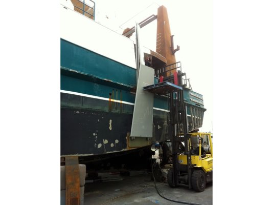
The wing is "square" ? Naca (it seams to be that on the photo below) ? Asymmetric section ?
Screenshot_2021-05-27-08-32-23-612~2.jpg


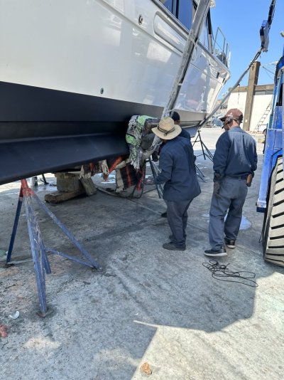
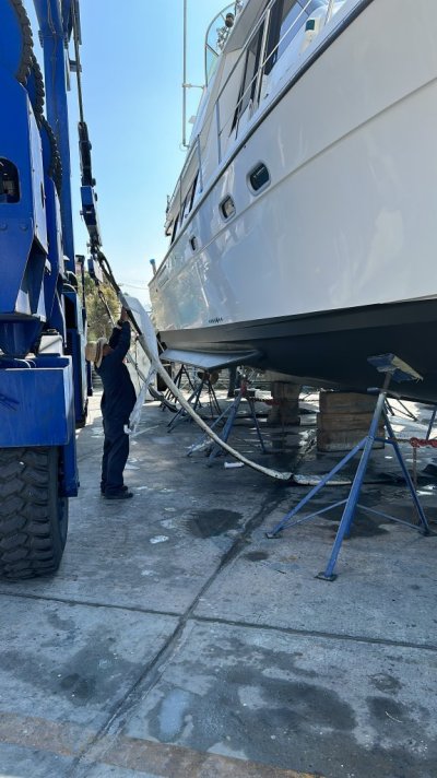
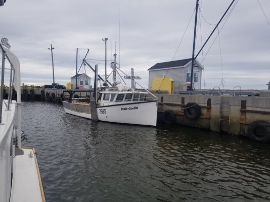
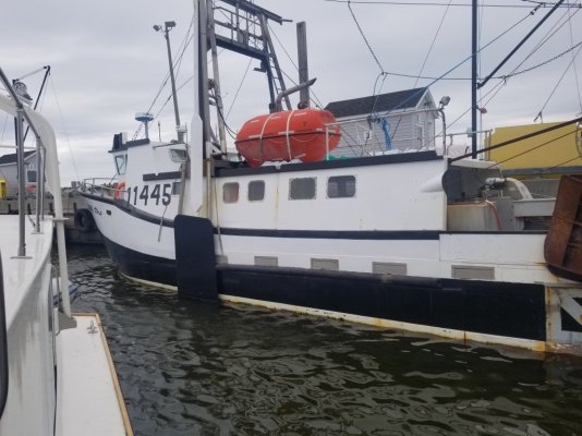
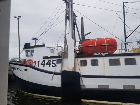
On the photo below you can see where (the red line) we could fit that , it seam may be too much forward but is exactly at the same level than the actual fin.
20220613_072126 - Copie (2).jpg

And at this level we have the forward bulkhead of the engine room and also high structure to fit the "sliding part".

But we make a batwing at this place it can be only fitted 30 cm below the wl, if we want fit it more deeper (for example on the actual structure of the fin 15mm tick with big stiffener behind may be T200x100)
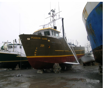
we must make a wing like the first photo : with an angle in this case could be more 65 cm below wl.

First I think fit the "sliding part" only on the withe upper part (because it will be an "elegant" solution, this white part is 10 cm "deeper" than the grey one and the sliding part not "overhang the grey part), unfortunately in this part the available length is only 1950 mm...not enough to bring back the wing near the hull... (except if we use one fixed part + a ram but it is not KISS ...)

If someone have detailled infos welcome !
 
Check out Project Brupeg on Youtube. They are rebuilding a sunken trawler into an expedition vessel and added that type of stabilizer.
 
An easy, relatively inexpensive addition to many hulls is something called "Rolling Chocks" or "Bilge Keels"

These are fins or keels if you will that are generally at an approx 45 degree angle in the water from the hull.

Mine are 12" X 24' and are highly effective at reducing rolling at anchor and under way.
 

Attachments

  • IMG_5358.jpeg
    IMG_5358.jpeg
    193.5 KB · Views: 40
  • IMG_5352.jpeg
    IMG_5352.jpeg
    198.1 KB · Views: 38
  • F42AAA54-B2B7-4440-B9E0-15221BF84B1F.jpeg
    F42AAA54-B2B7-4440-B9E0-15221BF84B1F.jpeg
    137.5 KB · Views: 42
  • IMG_5400.jpeg
    IMG_5400.jpeg
    179.5 KB · Views: 40
You might want to check this paper which has a lot of information about them. There is also an Australian paper. I'd assume you would use a symmetric NACA section as they work in both up and down motion. On a metal boat, pretty easy to retrofit I think. In the paper, they worked less well than fish, but an interesting finding on the fish was that a fair amount of their effect was simply from the destabilizing effect of all the gear required - even if the fish weren't deployed.
 
After open the file, it is one I read, and the compraison was not so bad with the " fish"
Yes on métal boat could be easier to fit the biggest problem will be make àn accurate...drawing :)
 
Interesting article.
So how do you figure out what shape your fins would be and how big and where on the hull they're mounted? Is the foil shape asymmetrical?
I think you're saying that you can only mount the wing pivot 30cm (12") below the waterline. Is that deep enough? Sounds pretty shallow.
I think I remember reading somewhere that the ideal location for paravanes was 2/3 of the way aft. I'd assume that fins would be about the same. There was a Garden boat up here that had paravanes retrofitted. The owner just used the existing mast which was forward of centerline. They found that when motoring the paravanes had enough downforce that they prevented the bow from rising to meet a sea. So the ride was wetter and uncomfortable.

I'd expect you want them somewhere close to the center of rotation in pitch to avoid exactly that situation you described. 2/3 aft is probably a good ballpark estimate on a lot of boats and a little too far aft is likely to be better than too far forward.
 
I don't know why you'd make them anything but a symmetric foil. They develop an angle of attack only due to the roll of the boat and the boat rolls both directions. I don't see an issue with the pivot point being close to the waterline, as they can angle downward into deeper water. You'd prefer they did not break the surface on the deeper rolls. One challenge in design is you most likely want a zero angle of attack with no roll, that may be hard to determine. But since they'd be metal, you could alter them pretty easily.

I've wondered if these can be made more effective by allowing some rotation of the wing, similar to a tacking centerboard on a racing sailboat. Lift (and therefore antiroll torque) is proportional to angle of attack. The foil only generates an angle of attach because the rolling motion of the boat moves the foil across the flow field, its local flow is the vector sum of the forward motion and the rolling motion. The faster the roll, the higher the angle of attack and higher the resisting force. On a tacking centerboard, the foil is allowed to rotate a small amount, perhaps 5 degrees. The pivot point is behind the center of effort so that on each roll reversal, the foil adopts a higher angle of attack and more restoring force. All a passive system, no control is needed. I suppose there may be problems with instability or banging the stops or other. We need someone to fund a study :).
 
It might be an issue with overhead height in Europe, but I think outriggers with stabilizer fish you drag is a much more elegant solution.

-Likely cheaper to fabricate
- The lever arm of getting them out away from the boat allows for much less surface area of the fish to still be effective.
-When not in use underway, and at the dock, there is nothing in the water causing drag, or corrosion, or marine growth.
- They are more common, and less likely to negatively affect resale value of the boat.
-Can be used at anchor with different flopper stopper plates to dramatically reduce roll. Will also encourage others to leave you space when at anchor.
- They look salty and cool.
IMG_2247 (1).jpeg
 
These photos may provide inspiration. From a tour of a fishing harbour in the Gaspe region.
 

Attachments

  • 20210714_152424.jpg
    20210714_152424.jpg
    132.8 KB · Views: 20
  • 20210714_152420.jpg
    20210714_152420.jpg
    127.2 KB · Views: 21
  • 20210714_161940~2.jpg
    20210714_161940~2.jpg
    109.6 KB · Views: 22
  • 20210714_152539.jpg
    20210714_152539.jpg
    115.7 KB · Views: 21
  • 20210714_152408.jpg
    20210714_152408.jpg
    146.7 KB · Views: 20
  • 20210714_152449.jpg
    20210714_152449.jpg
    136.2 KB · Views: 23
  • 20210714_152438.jpg
    20210714_152438.jpg
    105.1 KB · Views: 19
Thanks for all your answer.
- For the weight not sure it will be more than the rigging we saw for some "fish".
- The use will be easier , by far, than the fish
- the drag up will be same or even less than the actual "fin"
- could be fitted deeper , but with an angle in the "batwing", in this case could be fitted in place of the actual fin, with their 2 T frame 200x 100x 12 and a plating is at this place around 15/16 mm
- the position (red line) is useful because : at the same place than the actual fin (I presume designer definite this place), at this place the upper structure to fit the "sliding part" is already here and strong.
- the weight for example in alloy (but could be made in lighter material may be better because in case of "hit" it will be destroyed before...the hull :) ) if keep the same proportion than on the photo 2/3, 1/3 from the fixation could be lenght total 2.4 m by ( may be) 6/700mm. In this case the weight of the "wing" could be around 56 kgs (if 5 mm tick) 47kgs (if 4mmtick) with a pipe (say because don't make the drawing with NACA) 40x5 on the front , stiffener 70x 15 at the center ( where fix ) the axe, some small plate for the section, and flat bar 50x10 at the end.
It mean up+ the slide ( around 25 kgs if made rectangular pipe 100x50x10 and the "arm") I will arrive at a similar weight than the actual fin is 80kgs.

The result will be for one side 142.50kg/m x 2 around 290kg/m
For the stability if I put the life raft and the outboard down from the fly to the main deck it will compensate this.
And for the "resale value" ( first need to find a customer :)) ) anyway in one half day you can remove that and nothing remain exept the "sliding part" who could be removed also with a "disqueuse" but take more time.
 
I think you should take it a step further, and you will have this. Move them to the front and rear, add thousands of HP, and Shazam! We rode these on Lake Como, quite a fun experience. :D

 
Last edited:
Whilst talking of devices that reduce role, this is another video series I enjoy, especially since this particular delivery originated in Hamilton Island Australia, where I had just received one of the worst sun burns I had in decades. Never seen this on a Fleming...


Screen Shot 2024-04-18 at 7.56.56 AM.png
 
-When not in use underway, and at the dock, there is nothing in the water causing drag, or corrosion, or marine growth.
The batwings mostly retract out of the water. Only the hinge and a very short section of them is wet when they are folded.
 
Au Québec, ils appellent ça "un aileron à charnière".
 

Attachments

  • aileron a charniere.jpg
    aileron a charniere.jpg
    106.6 KB · Views: 11
  • aileron repliable.png
    aileron repliable.png
    172.1 KB · Views: 12
  • Fabrication-stabilizer-wings_w800.jpg
    Fabrication-stabilizer-wings_w800.jpg
    48.9 KB · Views: 10
The pictures are from a commercial long liner based in Eastern Australia. I don’t have one when there are fully deployed. They do look heavy.
IMG_9091.jpeg
IMG_9092.jpeg
IMG_9093.jpeg
 
Back
Top Bottom