- Joined
- Aug 29, 2012
- Messages
- 2,680
- Location
- Good Ol' US of A!
- Vessel Name
- Pau Hana
- Vessel Make
- 1989 PT52 Overseas Yachtfisher
Comments and guidance welcome!
I installed a Samlex 3000W inverter charger (pure sine wave) and am now ready to tap it into the house A/C panels.
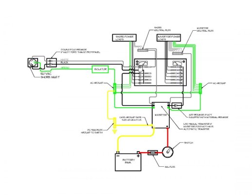
My thought process- in the cutrent configuration, Pau Hana has a single 50A 125/250V shorepower feeding an isolation transformer that splits the incoming power to feed panel 1 (normal loads, including the battery charger), and panel 2 (auxiliary loads). All is breakered properly, and can be fed thru the genset as well.
Plan- relocate inverted loads (outlets, ice maker, etc) to panel 2 and rewire 1 output leg (black) from the iso transformer to pass thru the inverter/charger so only panel 2 is powered by the inverter.
The genset output to panel 2 will also be routed thru the inverter charger so when the genny is on, the internal transfer switch will shut down inverting.
Just gotta figure out the ground and neutrals...
I installed a Samlex 3000W inverter charger (pure sine wave) and am now ready to tap it into the house A/C panels.
My thought process- in the cutrent configuration, Pau Hana has a single 50A 125/250V shorepower feeding an isolation transformer that splits the incoming power to feed panel 1 (normal loads, including the battery charger), and panel 2 (auxiliary loads). All is breakered properly, and can be fed thru the genset as well.
Plan- relocate inverted loads (outlets, ice maker, etc) to panel 2 and rewire 1 output leg (black) from the iso transformer to pass thru the inverter/charger so only panel 2 is powered by the inverter.
The genset output to panel 2 will also be routed thru the inverter charger so when the genny is on, the internal transfer switch will shut down inverting.
Just gotta figure out the ground and neutrals...