- Joined
- May 11, 2019
- Messages
- 3,462
- Location
- United States
- Vessel Name
- Muirgen
- Vessel Make
- 50' Beebe Passagemaker
We are cruising down the West Coast of Mexico, enroute to the Panama Canal.
The issue we are having is that for some reason, the marina power in the last three marinas we've stayed at has been really high voltage (Marina Mazatlan, Marina Fanatur, San Blas, and Marina Riviera Nayarit, La Cruz) averages voltage between 132vac and 137vac.
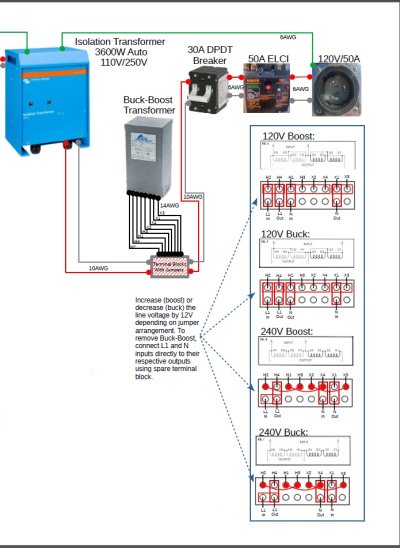
Now to the problem. We have a Victron Isolation Transformer 3600, and a Victron Quattro 12/5000 Inverter Charger.
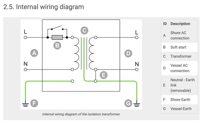
The Victron Isolation Transformer passes power through with a 5% INCREASE in voltage (to compensate for low marina voltage) according to the manual. So, for example, if the Pedestal voltage is 120vac, the output from the Isolation Transformer will be 126vac. Not a problem most of the time.
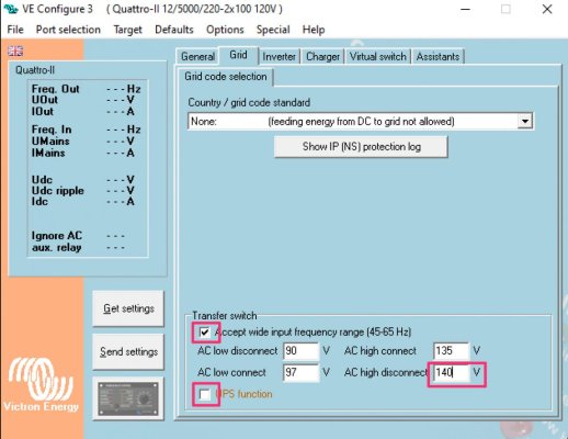
Now to the problem. The Victron Quattro 12/5000 will accept input voltage from 90vac to 140vac. Sooooooo when the dock voltage is > 135vac (and in reality, it appears that the high limit acceptable vac is really about 138 or so for the Quattro), the output voltage voltage from the Victron 3600 isolation transformer exceeds the allowable input voltage (138vac ish), and the Victron Quattro refused to pass through voltage, and also refuses to charge the batteries . . . .
So, for the 80% or so time during the 24 hour period that the dock voltage is at it's highest, we can't utilize the dock power . . . .
From what I understand, the 5% "overage" is hard wired into the Isolation Transformer as a function of the number of coils, or windings, so that cannot be changed. Also, the allowable voltage in the Quattro Inverter Charger is not changeable (nor would I really WANT to change that)
Anyone have any ideas of a solution or workaround?
The issue we are having is that for some reason, the marina power in the last three marinas we've stayed at has been really high voltage (Marina Mazatlan, Marina Fanatur, San Blas, and Marina Riviera Nayarit, La Cruz) averages voltage between 132vac and 137vac.
Now to the problem. We have a Victron Isolation Transformer 3600, and a Victron Quattro 12/5000 Inverter Charger.
The Victron Isolation Transformer passes power through with a 5% INCREASE in voltage (to compensate for low marina voltage) according to the manual. So, for example, if the Pedestal voltage is 120vac, the output from the Isolation Transformer will be 126vac. Not a problem most of the time.
Now to the problem. The Victron Quattro 12/5000 will accept input voltage from 90vac to 140vac. Sooooooo when the dock voltage is > 135vac (and in reality, it appears that the high limit acceptable vac is really about 138 or so for the Quattro), the output voltage voltage from the Victron 3600 isolation transformer exceeds the allowable input voltage (138vac ish), and the Victron Quattro refused to pass through voltage, and also refuses to charge the batteries . . . .
So, for the 80% or so time during the 24 hour period that the dock voltage is at it's highest, we can't utilize the dock power . . . .
From what I understand, the 5% "overage" is hard wired into the Isolation Transformer as a function of the number of coils, or windings, so that cannot be changed. Also, the allowable voltage in the Quattro Inverter Charger is not changeable (nor would I really WANT to change that)
Anyone have any ideas of a solution or workaround?