Adding Inverter to Existing System?

The friendliest place on the web for anyone who enjoys boating.
If you have answers, please help by responding to the unanswered posts.

Serene

Senior Member
Joined
Aug 18, 2014
Messages
340
Location
Australia
Vessel Name
Serene
Vessel Make
Blue Seas 36
I am looking to add an inverter to an existing system, but am not sure where/how it is wired in with minimal changes.

By way of description I have added a diagram below and will explain here;

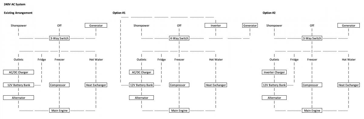
1. There is a three-way switch to select AC sources, between shore, generator and off.

2. There are four AC 'loads' which can be individually switched when either shore or generator AC is available. The fridge (12V/240V), freezer (engine/240V) and hot water (engine/240V) all have alternate sources when AC is not available.

3. When either shore or generator are providing AC power, there is an AC/DC charger which is connected to the 12V batteries to charge them, but note this is plugged into one of the multiple 240V AC outlets wired into the boat, so either all outlets + charger are live, or the outlets and charger are all disabled.

Now when I want to add the inverter I am not sure where it gets wired into this system.

Option #1 - Does it get added as an extra 'source'? But then my issue is I can see the 12V batteries providing power to the Inverter which converts it to 240V AC, which then flows back to the outlets and back into the 12V batteries via the AC/DC charger. This will obviously create an issue. But in this scenario the other three AC loads would all be powered with no changes.

Option #2 - Replace the AC/DC charger with an Inverter/Charger, which would charge when AC is present, and invert when it isn't. But in this case how does the AC current flow back to the AC loads? (outlets, fridge, freezer, hot water) And how does an Inverter/Charger know when the AC is coming from shore or generator vs coming back from itself as inverted power?

What is the most elegant way to add an Inverter with minimal change to the existing system?

I don't need the Inverter to power the fridge, freezer or hot water loads, but do want all outlets to be live when inverting. Basically I want access to power lower AC loads via the inverter when not on shore power, without having to start the generator.

Here is the diagram to help understand the situation.
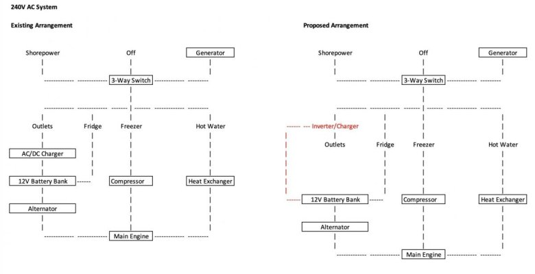
 

Attachments

  • Image 9-10-2023 at 5.26 pm.jpg
    Image 9-10-2023 at 5.26 pm.jpg
    40.3 KB · Views: 40
Part of the equation depends on how large an inverter you're getting. Many of the medium and larger ones with built-in battery chargers, also have transfer switches (relays). So the switchable outlets are on the transfer switch. When shore power or the generator are sensed by the inverter / battery charger, power flows through the unit to the outlets. When shore power or generator are absent, the inverter powers the outlets through the transfer switch. The inverter/ battery charger is wired where it only sees power from either the shore power or the generator.

Ted
 
I am not fully understanding your diagram. Maybe A wiring diagram would be better.

All I can say, I would go with a charger/inverter to keep it simple.

My boat, when I bought it used was wired like this and I do like it. From the AC panel main break, feeds the 3000W charger/inverter. To the charger/inverter input. The output is feed only to outlets, which is fine in my case. This feeds the microwave, coffer pot and anything I can plug in. This could power a freezer as in your case. Mine is both AC and DC inputs so powering from the inverter is not needed.

Hot water can be suppled from the engine or the genset. Not a big deal if not from the inverter. I can run the genset for hot water and charge the batteries at the same time.


As mention, how big of a inverter or changer/inverter or you installing? The size would dictate how and what would be powered and wired.
 
Last edited:
What Ted said.

When we added a "whole house" inverter/charger to this boat, it was a relatively simple replacement for the original thruster bank charger. The inverter's internal transfer switch does all the power management. Shore or genset power present? Pass through. Not present? Invert.

We made it so ours services the AC-only fridge, AC-only freezer, microwave, entertainment center (TV, etc.), and all the standard outlets. Those connections are all made in the AC panel, so individual breakers work as before (e.g., microwave breaker normally OFF until we intend to use it.)

Our heavier appliances -- aircons, water heater, cooktop -- are all 220VAC, so they're not included in that plan. Our washer/dryer combo is 120VAC, but I see no reason to service that with the inverter.

-Chris
 
Last edited:
I have Option 2. That allows the inverter loads to be chosen. There is instant switching from shore/GEN to inverter.

Option 1 the inverter is feeding everything and you will have to manually turn off items to avoid overload. I like the auto switch in the inverter charger but that only works if the input comes from shore or GEN. Option 1 does not feed through inverter and shore and GEN are OFF.

You have ACDC charger in Option 1, it can be left ahead of the Inverter charger, so it is not a load on inverter charger.
 
Before you get ahead of yourself with the wiring details, back up and look at some basics. Determine what you want to power with the inverter, total up that load to determine the wattage of the inverter. From that you can determine the battery bank size, then the charging requirements. You need to get the big picture; it's all part of a system, and it all is interdependent. So "adding an inverter to an existing system" isn't just a matter of adding the inverter. Everything in the system can change with a single change of one of that system's component parts. If you look at it with tunnel vision, you'll be constantly chasing down the gremlins that invade the part of the system you overlooked at the outset.

Are you going to expand the house bank capacity? Will your engine charging gear be up to the task of recharging an expanded bank? Will you have staged charging? Can you control the charge rate of the engine? Will you want to completely recharge while under way? Will your engine charging be tasked with providing power for the inverter to power loads while under way? Will you consider solar? (Highly recommended if you're planning to spend any time at anchor and want to fully charge the house bank.) Is your base 12v cabling adequate? (unlikely) The devil's in the details. The more homework you do ahead of the install, the fewer gremlins you'll have to deal with later.
 
An inverter/charger has separate input and output terminals. It cannot sense it's own output because there's never input on it's output terminal. If there was, it would let out the magic smoke and it won't work anymore. (That's electricianese for you fried it.) Typically you would have a breaker in the panel that powers up the I/C, sized for the I/C's pass through capability. That's connected to the I/C's input. The output goes to the breakers you want to power with the inverter. When shore or gen is connected and the inverter breaker is on, it passes current through as if it wasn't there. When you unplug, it goes to invert mode and powers only those circuits you connected to it's output. The only real modification you need to do is to add an additional neutral buss (the white wires) for the loads you have connected to the inverter. They should not be common with the non inverter circuits. One caveat with inverter/chargers: always turn the inverter or master selector switch off before connecting to a new shore power outlet. If it's a newer installation with an ELC (kind of like the GFI outlets in your home) installed, it might trip the ELC. Depending on how they set it up, that might take down just your outlet, or the whole dock, or the whole marina. You won't make friends that way.
 
What is the most elegant/simple way to add an Inverter with minimal change to the existing system?

I don't need the Inverter to power the fridge, freezer or hot water loads, but do want all outlets to be live when inverting. Basically I want access to power lower AC loads via the inverter when not on shore power, without having to start the generator.
=========================================

Years ago while cruising, installed a combined charger/inverter and worked flawless, liked the simplicity and functionality.

When I outfitted my current boat 4 years ago, my needs are different, most tied up at marinas with full access to power.

When not, either under way or anchor, likely use a microwave, a toaster, and most important AC chargers for all the electric gizmos, like shaver, tooth brush, cell phones, IPad,laptops,electronic portable charts.

Decided the most economical and simple option was to wire an inverter, freestanding.

I do not need to power all outlets, it can be done, but I don't need to power all of them.

The microwave is always connected to one of the outlets in the inverter.
The other outlet is connected to a regular, household with several outlets.

On it connect the toaster when I require, the multiple electronic gizmos with their individual chargers.

To add more charging low drain things like cell phones etc.,have a small plug in 12 volts car type of inverter.


My house load has 4 12 volts AGM size 31 with a total power of 400 amps.

powers a 3000 watts inverter but need to make sure when the microwave is on do not connect the toaster, otherwise the small electronics do fine.

=====================================
However, the most important factor to consider is the Inverter must be powered by the batteries, and here is the must-do.
Cable size from batteries bank to inverter.

Size is huge, like
"What size cable should I run for a 3000w inverter?
1/0 AWG
The best option for a 3000-watt inverter cable is a 1/0 AWG (American Wire Gauge) battery cable.Feb 16, 2022"

And size is related to distance between battery bank and inverter.


You need to size correctly, otherwise the inverter will trip.

Details as to correct fusing will leave out, am sure you are familiar.

Good luck
 
Lots of reading here. Thanks for the replies. Will come back with more questions if needed.
 
Part of the equation depends on how large an inverter you're getting. Many of the medium and larger ones with built-in battery chargers, also have transfer switches (relays). So the switchable outlets are on the transfer switch. When shore power or the generator are sensed by the inverter / battery charger, power flows through the unit to the outlets. When shore power or generator are absent, the inverter powers the outlets through the transfer switch. The inverter/ battery charger is wired where it only sees power from either the shore power or the generator.

Ted

Thanks Ted. Have been doing lots of reading and understand the auto switching. Just trying to figure out where to wire it into my system with minimal changes.

Still working out sizing. It is a debate between large enough to power all of the most likely inverted loads vs small to just use for the things when not on shore power or the generator is not running, such as phone chargers, etc. When not on passage and the main engine isn't running, I can use the generator for the hot water and keeping the freezer temp down, so not worried about those loads.

I have 600Ah of AGM batteries, so not lithium and not a huge capacity. I think I will be limited to drawing 60A from this bank, which at 12V is only 720W.

I have the spec sheet for my batteries and it states maximum discharge current 2,000A (5 seconds) which sounds like a useless specification as it is limited to only five seconds.

There is no sustained discharge current listed, but does state recommended maximum charging current to be 60A thus working off the assumption that 60A is also the recommended sustained discharge current.

Does this make sense?
 
Last edited:
Before you get ahead of yourself with the wiring details, back up and look at some basics. Determine what you want to power with the inverter, total up that load to determine the wattage of the inverter. From that you can determine the battery bank size, then the charging requirements. You need to get the big picture; it's all part of a system, and it all is interdependent.

[SNIP]

All good points and understand your comment about the bigger picture. In this case though I am not wanting to change anything else (if possible) and just add an inverter to power some smaller loads.

No plans on changing batteries, alternator or adding solar at this stage. I have 600Ah of AGM, a Balmar 100A externally regulated alternator, a 60A AC/DC charger and a 6kW generator which are all working fine.

Overnight I use about 20% of capacity, so am limited in the number of days I can stay at anchor, but at anchor have to run the generator anyway to heat water for the evening shower and keep the freezer temp down.

See post above about maximum discharge current, which I feel will be my limiting factor.
 
For short term loads (such as running a microwave, coffee maker, or toaster for a few minutes at a time) you can probably pull more like 100 - 120 amps comfortably from your AGMs. The limiting factor will be when you see too much voltage sag under those loads. I wouldn't try to pull 100 amps for an hour from that bank, but for 3 - 5 minutes you won't hurt the batteries.
 
For short term loads (such as running a microwave, coffee maker, or toaster for a few minutes at a time) you can probably pull more like 100 - 120 amps comfortably from your AGMs. The limiting factor will be when you see too much voltage sag under those loads. I wouldn't try to pull 100 amps for an hour from that bank, but for 3 - 5 minutes you won't hurt the batteries.

Makes sense. Thank you. I do have a coffee maker and a toaster I will want to use with inverted power, but not a microwave. Maybe something added at a later date though.
 
An inverter/charger has separate input and output terminals. It cannot sense it's own output because there's never input on it's output terminal. If there was, it would let out the magic smoke and it won't work anymore. (That's electricianese for you fried it.) Typically you would have a breaker in the panel that powers up the I/C, sized for the I/C's pass through capability. That's connected to the I/C's input. The output goes to the breakers you want to power with the inverter. When shore or gen is connected and the inverter breaker is on, it passes current through as if it wasn't there. When you unplug, it goes to invert mode and powers only those circuits you connected to it's output.

[SNIP]

This scenario makes sense. I will need to draw it out on my diagram (yes I know not a proper wiring diagram) to fully understand how to implement it though. Thank you.
 
What is the most elegant/simple way to add an Inverter with minimal change to the existing system?

I don't need the Inverter to power the fridge, freezer or hot water loads, but do want all outlets to be live when inverting. Basically I want access to power lower AC loads via the inverter when not on shore power, without having to start the generator.
=========================================

Years ago while cruising, installed a combined charger/inverter and worked flawless, liked the simplicity and functionality.

When I outfitted my current boat 4 years ago, my needs are different, most tied up at marinas with full access to power.

When not, either under way or anchor, likely use a microwave, a toaster, and most important AC chargers for all the electric gizmos, like shaver, tooth brush, cell phones, IPad,laptops,electronic portable charts.

Decided the most economical and simple option was to wire an inverter, freestanding.

I do not need to power all outlets, it can be done, but I don't need to power all of them.

The microwave is always connected to one of the outlets in the inverter.
The other outlet is connected to a regular, household with several outlets.

On it connect the toaster when I require, the multiple electronic gizmos with their individual chargers.

To add more charging low drain things like cell phones etc.,have a small plug in 12 volts car type of inverter.


My house load has 4 12 volts AGM size 31 with a total power of 400 amps.

powers a 3000 watts inverter but need to make sure when the microwave is on do not connect the toaster, otherwise the small electronics do fine.

[SNIP]

This scenario could work too. Have to think about it a bit more.
 
[SNIP]

However, the most important factor to consider is the Inverter must be powered by the batteries, and here is the must-do.
Cable size from batteries bank to inverter.

Size is huge, like
"What size cable should I run for a 3000w inverter?
1/0 AWG
The best option for a 3000-watt inverter cable is a 1/0 AWG (American Wire Gauge) battery cable.Feb 16, 2022"

And size is related to distance between battery bank and inverter.


You need to size correctly, otherwise the inverter will trip.

Details as to correct fusing will leave out, am sure you are familiar.

Good luck

Yes understand the relationship between Amps, distance and wire size. The current 60A charger is only about 1.5m (5') from the battery bank and is wired to handle 60A, so would put the Inverter/Charger in the same place.

If limited to a 720W inverter no wiring change would be required.

Of course if I use a larger inverter I will need to measure the existing wiring to see what it's size is to determine load capacity and possibly increase battery bank capacity. But that's down the track. Just trying to understand where/how to insert the inverter into the system.
 
Serene
Your thinking seems pretty good with a bit of scattered TF feedback. To close the information loop I suggest two go to marine electrical experts:
- Marine How To website
- Nigel Calder website and writings
 
An inverter/charger has separate input and output terminals. It cannot sense it's own output because there's never input on it's output terminal. If there was, it would let out the magic smoke and it won't work anymore. (That's electricianese for you fried it.) Typically you would have a breaker in the panel that powers up the I/C, sized for the I/C's pass through capability. That's connected to the I/C's input. The output goes to the breakers you want to power with the inverter. When shore or gen is connected and the inverter breaker is on, it passes current through as if it wasn't there. When you unplug, it goes to invert mode and powers only those circuits you connected to it's output.

[SNIP]

Will play this back to check if I have it right. Have also attached a new diagram.

1. Remove the existing AC/DC charger.

2. Add the new Inverter/Charger into the system, between the three way switch and the breaker for 'outlets' only. Leaving the other three breakers (fridge, freezer & hot water) separate.

3. Wire up the Inverter/Charger to the 12V battery bank.

Working scenarios are as follows;

1. Shore power or generator
a. Three way switch set to 'shore' or 'generator'
b. 240V AC available to all four breakers
c. Inverter/Charger passes AC to the outlets and charges the 12V battery bank if needed and excess capacity available that isn't being used by the outlets.
d. If AC load is greater than shore power or generator can provide, the Inverter/Charger supplements by drawing current from the 12V battery bank and inverting it back to the outlets. But in this scenario this only works for the outlets. If the hot water, fridge and freezer need more than shore power or generator can provide there is a problem. But not really a problem as the generator is sized to run all loads concurrently, so in theory will never happen.

2. No shore power and generator not running
a. Three way switch set to 'off'
b. Inverter/Charger senses no AC input, so takes 12V DC and inverts it to pass to the outlets. No 12V battery bank charging available in this scenario and no hot water, fridge or freezer available.

Does this sound right?
 

Attachments

  • Image 10-10-2023 at 10.22 am.jpg
    Image 10-10-2023 at 10.22 am.jpg
    51.7 KB · Views: 18
Last edited:
Serene
Your thinking seems pretty good with a bit of scattered TF feedback. To close the information loop I suggest two go to marine electrical experts:
- Marine How To website
- Nigel Calder website and writings

Thanks sunchaser. I am familiar with Nigel Calder, but need to look at 'Marine How To'.
 
Thanks Ted. Have been doing lots of reading and understand the auto switching. Just trying to figure out where to wire it into my system with minimal changes.

Still working out sizing. It is a debate between large enough to power all of the most likely inverted loads vs small to just use for the things when not on shore power or the generator is not running, such as phone chargers, etc. When not on passage and the main engine isn't running, I can use the generator for the hot water and keeping the freezer temp down, so not worried about those loads.

I have 600Ah of AGM batteries, so not lithium and not a huge capacity. I think I will be limited to drawing 60A from this bank, which at 12V is only 720W.

I have the spec sheet for my batteries and it states maximum discharge current 2,000A (5 seconds) which sounds like a useless specification as it is limited to only five seconds.

There is no sustained discharge current listed, but does state recommended maximum charging current to be 60A thus working off the assumption that 60A is also the recommended sustained discharge current.

Does this make sense?

Let me add a couple of things.:

First if you look behind the breaker panel and determine the pathway of the circuits going to the breaker panel that you may want to use on the inverter, you may be able to add another breaker panel without lengthening wires. This panel would be a sub panel that connects to the inverter transfer switch. It may be limited by the capacity of the transfer switch. This concept is often done for home generators that can't power the whole house, so only circuits used with the generator are on the sub panel.

Don't undersize your inverter for 2 reasons. At some point you may increase your house battery capacity. Secondly, when underway, the engine alternator allows you to increase the output of your inverter. On my boat the alternator that charges my house bank is 220 amps. The inverter can convert most of those amps giving me about 3 KW while underway. This allows me to do laundry with an all in one washer dryer while underway.

Do more research before investing to prevent limiting yourself.

Ted
 
I did mine as the option with what OP calls 4-way switch. OC Divers suggestion of putting the inverter/charger inline certainly works, but I wanted separation of sources. With inverter inline, if shore power trips, power comes from batteries which may not be obvious. Not a big deal either way, just how I chose to do it. I have lock-oit sliders on the breakers (pic attached) but a rotary switch would do the same. Pretty easy to wire. I also have on/off for the inverter through one of the panel breakers.

Peter466672422.jpg
 
Last edited:
Let me add a couple of things.:


First if you look behind the breaker panel and determine the pathway of the circuits going to the breaker panel that you may want to use on the inverter, you may be able to add another breaker panel without lengthening wires. This panel would be a sub panel that connects to the inverter transfer switch. It may be limited by the capacity of the transfer switch. This concept is often done for home generators that can't power the whole house, so only circuits used with the generator are on the sub panel.


Don't undersize your inverter for 2 reasons. At some point you may increase your house battery capacity. Secondly, when underway, the engine alternator allows you to increase the output of your inverter. On my boat the alternator that charges my house bank is 220 amps. The inverter can convert most of those amps giving me about 3 KW while underway. This allows me to do laundry with an all in one washer dryer while underway.


Do more research before investing to prevent limiting yourself.


Ted
I agree - larger inverter carries little cost premium. The biggest issue is cabling and circuit protection. Sweet spot with inverter/chargers these days is 3kw with 125a (+/-) charger. This is a really handy device. Future needs will only increase so might as well install and cable for the larger item now, even with a 600ah AGM bank (which I'm pretty sure can support discharge of much more than 70a).

Regardless of what you decide, you won't be sorry if you cable for a 3kw inverter.

Peter
 
I went for the inline inverter, but feeding a sub panel so some loads can't be powered from the inverter. If I'm in a situation where I don't want the inverter to take over if shore power fails, I just switch it to "charger only" mode. In that mode it'll pass power through and charge the batteries, but if shore/gen power drops the inverter just turns off. Most of the time we appreciate the seamless switch to inverter power when leaving the dock.
 
Go to the top right corner of the main Trawler Forum page and click on the Library tab. Go to the Miscellaneous section and look for "Installing an Inverter". This might provide a little help.
 
Go to the top right corner of the main Trawler Forum page and click on the Library tab. Go to the Miscellaneous section and look for "Installing an Inverter". This might provide a little help.

I didn't even know this library existed! Thank you.
 
Let me add a couple of things.:

[SNIP]

Don't undersize your inverter for 2 reasons. At some point you may increase your house battery capacity. Secondly, when underway, the engine alternator allows you to increase the output of your inverter. On my boat the alternator that charges my house bank is 220 amps. The inverter can convert most of those amps giving me about 3 KW while underway. This allows me to do laundry with an all in one washer dryer while underway.

Do more research before investing to prevent limiting yourself.

Ted

Thank you. I didn't think of the underway scenario with the alternator coming into play. Good tip. And yes still in 'education' mode before I purchase any equipment. Thus the thousand questions!
 
[SNIP]

With inverter inline, if shore power trips, power comes from batteries which may not be obvious.

[SNIP]

Another thing I hadn't thought about! And yes would not want batteries drained when plugged into shore power that fails. But am assuming an inverter can be smart enough to be set to a mode to not invert, just pass through. So can enable this mode when alongside and the boat is left for any period of time.

More research needed.
 
I agree - larger inverter carries little cost premium. The biggest issue is cabling and circuit protection. Sweet spot with inverter/chargers these days is 3kw with 125a (+/-) charger. This is a really handy device. Future needs will only increase so might as well install and cable for the larger item now, even with a 600ah AGM bank (which I'm pretty sure can support discharge of much more than 70a).

Regardless of what you decide, you won't be sorry if you cable for a 3kw inverter.

Peter

Very good advice. Thank you. LiFePo4 and PV charging are in my future, but one step at a time.
 
I went for the inline inverter, but feeding a sub panel so some loads can't be powered from the inverter. If I'm in a situation where I don't want the inverter to take over if shore power fails, I just switch it to "charger only" mode. In that mode it'll pass power through and charge the batteries, but if shore/gen power drops the inverter just turns off. Most of the time we appreciate the seamless switch to inverter power when leaving the dock.

Bingo. I was just about to go research this based off Peter's reply. No need to now, so thank you.
 
Bingo. I was just about to go research this based off Peter's reply. No need to now, so thank you.
To clarify, likely only want the AC outlets to be energized inline via the inverter output, not direct from shore power. Meaning these circuits (the AC outlets in this case) would be run through the inverter all the time, not switched. AC input into the inverter to power battery charger would have its own breaker fed from shore/generator power, not from the inverter of course.

Good luck with however you proceed. Inverters are great whether whole house or select circuits.

Peter
 
Back
Top Bottom