Right way to split wires?

The friendliest place on the web for anyone who enjoys boating.
If you have answers, please help by responding to the unanswered posts.

TheAtomicDog

Senior Member
Joined
Oct 30, 2020
Messages
157
Vessel Name
Salty Seagull
Vessel Make
SSP Type 211
Hey guys,

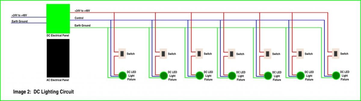
I am rewiring my boat from scratch. I have 4 DC lights in the forward cabin and 2 AC lights. This is about 5-6 meters from the panels. Assuming I run 1 wire from the panel for DC and one for AC into the main cabin, what is the right way to split them for the individual lights?

Thanks!
 
Here’s one way.

You’d also want the plastic covers that protect them.
 

Attachments

  • 992B731B-3428-4DE6-BD6F-A500CCDDF190.jpg
    992B731B-3428-4DE6-BD6F-A500CCDDF190.jpg
    71.7 KB · Views: 119
BTW, after seeing what you’re taking on, I will never again complain about having to drive 30 minutes to work on my boat or waiting a few days for parts. Best of luck; she’ll be amazing when you get done with her.
 
When you refer to "1 wire" are you using a flat duplex cable (1 red and 1 yellow wire) for the DC circuits and a flat triplex cable (1 black, 1 white and 1 green) for the AC? When I did a total rewire of my boat I used separate terminal blocks and heat shrink terminals for all AC & DC wire connections, bringing each device load to the terminal block. I would suggest you buy a good marine electrical manual such as John C. Payne's book The Marine Electrical and Electronics Bible. It is a wealth of information.
 
Are you going to put in both AC and DC powered lights? I only have DC powered LED lights in the boat. They are enough to see very well and this way I have the same lights available when not on shore power. Also makes the wiring much simpler. And with LED lights the wiring can be smaller too.
 
Geez guys... Most installations i have seen simply run power from one fixture to another from closest to furthest.

This way all the connections are accessible by simply pulling a light.
 
Here’s one way.

You’d also want the plastic covers that protect them.

Do you have a link or source for the terminal block covers? I sometimes make something but I'd happily buy a ready-made simple cover.
 
Geez guys... Most installations i have seen simply run power from one fixture to another from closest to furthest.

This way all the connections are accessible by simply pulling a light.

This!
 
Are you going to put in both AC and DC powered lights? I only have DC powered LED lights in the boat. They are enough to see very well and this way I have the same lights available when not on shore power. Also makes the wiring much simpler. And with LED lights the wiring can be smaller too.
I'm with Dave on this one... why bother with 120V lighting?
Put in all DC LEDs at whatever light Intensity you prefer. Some high lumens and some low give you flexibility.
If you have AC it provides DC via charger when connected and you have multi options of what to run while away from shore power.
LEDs are low power consumers and DC so why go any other way?
If you don't want to change out 120V fixtures just leave them in place, gut them and install LED. Lots of conversion kits & options available.
You save $ on wiring DV vs AC
 
Greetings,
I second Mr. BV's recommendation: "I would suggest you buy a good marine electrical manual such as John C. Payne's book The Marine Electrical and Electronics Bible.
I might add: https://www.amazon.com/Boatowners-Mechanical-Electrical-Manual-4/dp/0071790330


Edit: I seem to recall you don't want to run 12v and 110v wires in the same conduit/chase. Might be wrong on that...

That is correct, AC & DC wiring must be separated and can not be in the same conduit/chase. I also think having AC lighting is a thing of the past if DC lighting is available. I have only DC LED lighting and see no reason to have AC.
 
I think you will want to run the ac (3-wire) and dc (2-wire) cables from your power panel with gauge of sufficient size to power all the ac or dc lights you plan on having to terminal boards (TB) more or less central to where the lights will be. Each light, especially the dc ones can then have smaller gauge wiring than the main feed from the panel. I would install the TBs in plastic electrical boxes.
 
Do you have a link or source for the terminal block covers? I sometimes make something but I'd happily buy a ready-made simple cover.

Sorry, I assumed wrong. Blue Sea has covers for fuse blocks and bus bars—which I’ve used—but not, apparently, for terminal blocks. I’ve made large Lexan covers for clusters of terminal blocks where circuits are mated up, but I haven’t had a need for individual covers.
 
I use Blue Seas covers for terminal strips. Doesn’t matter what they call them as long as they fit , they will work. All they are are plastic covers with builtin standoffs so they will cover terminal blocks as well as other things.
 
Sorry, I assumed wrong. Blue Sea has covers for fuse blocks and bus bars—which I’ve used—but not, apparently, for terminal blocks.

Thanks for double-checking. I, too, use the bus bar covers which are simple and work well.

I contacted Blue Sea a few years ago and asked about terminal block covers (which they did not have at the time). They said they don't make the terminal blocks and they don't get them with covers. I said I hoped they would consider making some for the terminal blocks they sell anyway. So I was hoping they had.

I use Blue Seas covers for terminal strips. Doesn’t matter what they call them as long as they fit , they will work. All they are are plastic covers with builtin standoffs so they will cover terminal blocks as well as other things.

Which other covers are you using that fit? (Sounds like you are re-purposing one of their other covers - clever idea.)

To those who are finding/using Blue Sea terminal block covers: Do you have a part number? They usually assign a 4-digit part number to things they sell. I would definitely pick some up.

Thanks,
Frosty
 
Last edited:
I have used 2710 and 2701 for terminal block covers. Maybe not made specifically for terminal blocks but if they fit as terminal block covers, no problem.
 
No hidden splices or terminal blocks. All connections must be accessible. There is no need for AC and DC lights any more. DC only lights. AC receptacles. Pick up a Nigel Calder book.
 
Figuring out the wiring after your done for 2-5years and it goes dark can be a huge PIA.

Most places that sell old fashioned wired intruder alarms will have stick on number books.

Our technique is to number the circuit on the electric panel , and then the wire to the panel.

The same number is also on the wire near the user , and also on the user , light , radio whatever.

This system takes little time to install with the wires , but can save vast time when the lights go out.

A CB is sized to protect the wire , a fuse to protect the user.

https://www.bradyid.com/wire-cable-...MI5ruN7bbu7wIVF47ICh363w3qEAQYByABEgKu3PD_BwE
 
What some are suggesting here regarding terminal blocks might sound interesting but is is frankly not necessary or practical on many or most boats. It is also just not how things are generally wired by professionals.

A lighting circuit, starting at a overcurrent protective device is wired 100% in series from device to device with the connections to those devices being parallel connections to neutral for AC or ground for DC circuits.

This methodology is demonstrated time and time again in pretty much every thing that has lighting or outlets.

Why??? simple, it's easy to install, its inexpensive, its easy to work on, and it works.

A single circuit also MUST have ALL wires downstream of the overcurrent protective device rated for the full current rating of that device. You CANNOT run a larger wire to a terminal block and then smaller wires out from there.

Some here are giving out advice on subjects that they are frankly unqualified to give advice on, based on the fact that the advice given, if followed, creates a unsafe installation risking a fire, injury, or even death.
 
"Professionals," especially the ones who wire houses and just guys who get paid to work, and they do what is easiest within codes (hopefully). That doies not make it best practice for my boat. You can run all lights in a series circuit if you want them to all die through a single connection issue at the first light - go ahead, ask me how I know. Otherwise, branch off as previously suggested - that's why they invented fuse blocks.
 
This is what Kevin posted... "A lighting circuit, starting at a overcurrent protective device is wired 100% in series from device to device with the connections to those devices being parallel connections to neutral for AC or ground for DC circuits."


I am pretty sure he means one backbone wire from the source to each fixture but each fixture is parallel and not truly in a series circuit so one failure doesn't mean a system failure.


Plus not many resistance circuits of more than a few fixtures would really work as the effect on the last in the circuit would be undesirable.


The danger in that is if the total run in feet is substantial and a DC circuit, the voltage loss would require a wire run much larger than the fixture wires and require a different circuit protection device at the fixture. Not always ...but should be considered.


I apologize Kevin if I misunderstood your intent... but it is common in repair and manufacture even by the pros I know.


Picture courtesy of Google images.
 

Attachments

  • 2933531439673491175a.jpg
    2933531439673491175a.jpg
    44.4 KB · Views: 41
Last edited:
This is what Kevin posted... "A lighting circuit, starting at a overcurrent protective device is wired 100% in series from device to device with the connections to those devices being parallel connections to neutral for AC or ground for DC circuits."


I am pretty sure he means one backbone wire from the source to each fixture but each fixture is parallel and not truly in a series circuit so one failure doesn't mean a system failure.


Plus not many resistance circuits of more than a few fixtures would really work as the effect on the last in the circuit would be undesirable.


The danger in that is if the total run in feet is substantial and a DC circuit, the voltage loss would require a wire run much larger than the fixture wires and require a different circuit protection device at the fixture. Not always ...but should be considered.


I apologize Kevin if I misunderstood your intent... but it is common in repair and manufacture even by the pros I know.

Yes, your drawing is Exactly how every boat, every industrial circuit, and every house I have ever seen is wired.

That way all connections are accessible.


The idea of a larger wire to a terminal block, and then smaller wires from there is dangerous. Substitute a fuse panel for the terminal block and that's just fine.

The challenge is the terminal blocks discussed are just not necessary and often not practical for real circuits even if they use the same size wire. Boats are generally finished on the interior and now folks are going to bury a terminal block somewhere probably hidden and not accessible.

Thats why we run circuits like in your great drawing. One could theoretically say that at the end of the circuit the voltage might drop but from a practical standpoint that is not a real concern if you use the proper sized wire for the overcurrent protection device.
 
BTW, after seeing what you’re taking on, I will never again complain about having to drive 30 minutes to work on my boat or waiting a few days for parts. Best of luck; she’ll be amazing when you get done with her.

Thanks!
 
I have only DC LED lighting and see no reason to have AC.

I agree. However, the woman friend bought some very nice LED fixtures because I said we would only use LED/DC, but the ones she bought are AC. Bah. Anyway, there are actually 6 of them, all intended for the main berth. There won't be any more AC lights on the boat. I have asked the manufacturer if there is a way to get rid of the converter, but I suspect it's integral as they are quite small.
 
Look for the output of the AC power supply for the LED lights...to might be able to substitute a DC power source.
 
Hey guys,

Thanks for the great discussion. I am learning a lot. This is why I love this forum.

The picture psneeld posted actually illustrates my question. Where each of the wire branches to the individual fixture...how is that accomplished?
 
This is what Kevin posted... "A lighting circuit, starting at a overcurrent protective device is wired 100% in series from device to device with the connections to those devices being parallel connections to neutral for AC or ground for DC circuits."


I am pretty sure he means one backbone wire from the source to each fixture but each fixture is parallel and not truly in a series circuit so one failure doesn't mean a system failure.


Plus not many resistance circuits of more than a few fixtures would really work as the effect on the last in the circuit would be undesirable.


The danger in that is if the total run in feet is substantial and a DC circuit, the voltage loss would require a wire run much larger than the fixture wires and require a different circuit protection device at the fixture. Not always ...but should be considered.


I apologize Kevin if I misunderstood your intent... but it is common in repair and manufacture even by the pros I know.


Picture courtesy of Google images.

In the schematic, what is the blue control wire?
 
By the way, these arrived today!
 

Attachments

  • Victron.jpg
    Victron.jpg
    167.9 KB · Views: 12
Back
Top Bottom