albinalaska
Veteran Member
- Joined
- Jun 6, 2020
- Messages
- 94
- Location
- USA
- Vessel Name
- Sea Gypsy
- Vessel Make
- 1979 Albin Trawler 36'
Good Day!
I am in the process of designing new diesel fuel tanks for our vessels main tanks. Our 1979 Albin Trawler is equipped with two ~150gal diesel tanks that are in the worst shape I've seen on any vessel I've worked with. Our vessel also is quipped with two newer(ish) 25gal aux tanks running along the keel in the bilge.
On the lowest part of the forward face on the main tanks there are crusty old gate valves that each feed their own aux tank (aux tanks lead to the fuel filters/engines). Finally there is a fill port on the top farthest aft part of the tanks. There are no vents equipped on the mains. The vents are in the aux tanks. You would have laughed at how long it took for us to refuel bringing the vessel home to Alaska through the Inside Passage last summer... or cried.
These tanks have to go. They aren't bonded, there is rusty metal material flaking off and severe corrosion anywhere the chipped paint reveals.
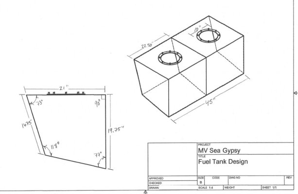
I have found a reputable company in Seattle to design the tanks based on a CAD drawing I was able to whip up (I'm no expert but I think it'll get the idea across) there are very specific angles and measurements so it required some leg work on my part.
We have settled on 316L SS and are satisfied that will give us many years of service but I'm curious about some design concepts if I can soundboard the hive mind here and get some advice?
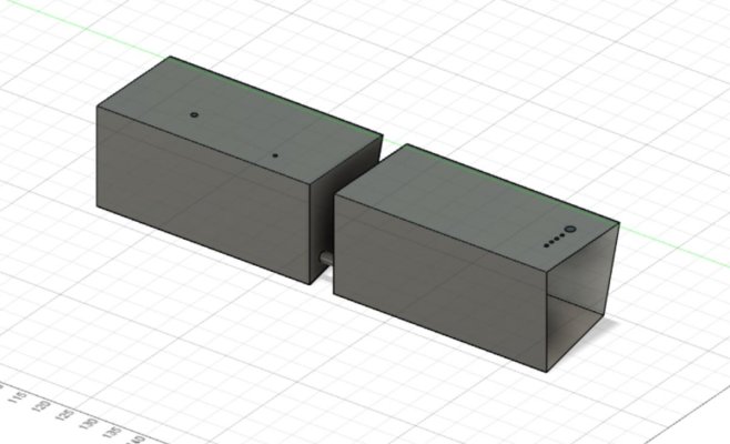
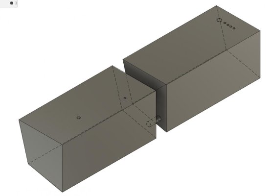
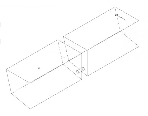
The 150gal tanks are too large to remove intact. They'll need to be clawed out of the engine room. The idea is that we would replace the two tanks with four smaller tanks (x4 75gal tanks) that are ported together (port and stbd respectively) with a 1" pipe fitting. These smaller tanks would give us the best chance at sparing the removal of the entire cabin floor.
You can check out the photos attached but the pickup would be near the back of the forward tanks so as to decrease the line run to the engines they'll be suppling.
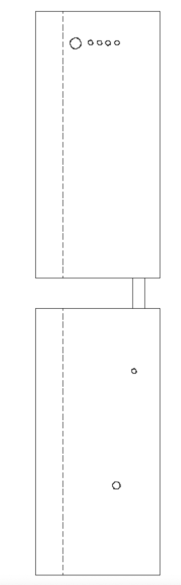
The fill port would be on the outboard side of the aft tank where the rest of the pickups to various fittings would be located. The SAE sensor gauge would be somewhere near the middle/front of the forward most tank. Finally our idea is to include 8" access ports on the topside of each tank (Two per tank) between each baffle to allow access and cleaning when the time comes.
Does anyone see any inherent flaws with this design concept? We are within spec for the baffles based on length and tank and from what I gather this is a fairly straight forward design. The company said there they just completed something very similar to this concept and said tanks come in many different shapes and sizes and pickup varieties with regards to tube placements base on each vessels need. While that is relieving in a way it's vague enough to have me wondering if I'm not missing something.
Could I not just put a single ball-valve fitting on the bottom vertical edge of the tanks and have those supply a manifold and spare all of the pickup tubes in the back of the aft tank? A manifold would be serviceable whereas there isn't enough clearance on top of the tank to pull the pickup tubes once installed.
Secondly - I'm sure this will receive some flak but - I've seen access hatches on the sides of tanks. Since we wouldn't be able to access any hatch on top of the tank would it be preferred to put the 8" hatch on the side of each tank and monitor for leaks? My instinct is that it's just asking for trouble down the line. But I've seen it and very diligent about maintenance.
Anyways - Long message but I would greatly appreciate any feedback or criticisms about this design.
Kyle
mvseagypsy@gmail.com
IG: @MV_SeaGypsy
Pictures show solo tank design and then some more general snapshots of the both tanks in sequence. They would be angled appropriately to the hull for the respective sides. Pics are stbd side.
I am in the process of designing new diesel fuel tanks for our vessels main tanks. Our 1979 Albin Trawler is equipped with two ~150gal diesel tanks that are in the worst shape I've seen on any vessel I've worked with. Our vessel also is quipped with two newer(ish) 25gal aux tanks running along the keel in the bilge.
On the lowest part of the forward face on the main tanks there are crusty old gate valves that each feed their own aux tank (aux tanks lead to the fuel filters/engines). Finally there is a fill port on the top farthest aft part of the tanks. There are no vents equipped on the mains. The vents are in the aux tanks. You would have laughed at how long it took for us to refuel bringing the vessel home to Alaska through the Inside Passage last summer... or cried.
These tanks have to go. They aren't bonded, there is rusty metal material flaking off and severe corrosion anywhere the chipped paint reveals.
I have found a reputable company in Seattle to design the tanks based on a CAD drawing I was able to whip up (I'm no expert but I think it'll get the idea across) there are very specific angles and measurements so it required some leg work on my part.
We have settled on 316L SS and are satisfied that will give us many years of service but I'm curious about some design concepts if I can soundboard the hive mind here and get some advice?
The 150gal tanks are too large to remove intact. They'll need to be clawed out of the engine room. The idea is that we would replace the two tanks with four smaller tanks (x4 75gal tanks) that are ported together (port and stbd respectively) with a 1" pipe fitting. These smaller tanks would give us the best chance at sparing the removal of the entire cabin floor.
You can check out the photos attached but the pickup would be near the back of the forward tanks so as to decrease the line run to the engines they'll be suppling.
The fill port would be on the outboard side of the aft tank where the rest of the pickups to various fittings would be located. The SAE sensor gauge would be somewhere near the middle/front of the forward most tank. Finally our idea is to include 8" access ports on the topside of each tank (Two per tank) between each baffle to allow access and cleaning when the time comes.
Does anyone see any inherent flaws with this design concept? We are within spec for the baffles based on length and tank and from what I gather this is a fairly straight forward design. The company said there they just completed something very similar to this concept and said tanks come in many different shapes and sizes and pickup varieties with regards to tube placements base on each vessels need. While that is relieving in a way it's vague enough to have me wondering if I'm not missing something.
Could I not just put a single ball-valve fitting on the bottom vertical edge of the tanks and have those supply a manifold and spare all of the pickup tubes in the back of the aft tank? A manifold would be serviceable whereas there isn't enough clearance on top of the tank to pull the pickup tubes once installed.
Secondly - I'm sure this will receive some flak but - I've seen access hatches on the sides of tanks. Since we wouldn't be able to access any hatch on top of the tank would it be preferred to put the 8" hatch on the side of each tank and monitor for leaks? My instinct is that it's just asking for trouble down the line. But I've seen it and very diligent about maintenance.
Anyways - Long message but I would greatly appreciate any feedback or criticisms about this design.
Kyle
mvseagypsy@gmail.com
IG: @MV_SeaGypsy
Pictures show solo tank design and then some more general snapshots of the both tanks in sequence. They would be angled appropriately to the hull for the respective sides. Pics are stbd side.
Attachments
-
 Screen Shot 2020-11-23 at 2.07.00 PM.jpg59.7 KB · Views: 35
 -
 Screen Shot 2020-11-23 at 2.19.19 PM.jpg36.1 KB · Views: 35
 -
 Screen Shot 2020-11-23 at 2.16.26 PM.jpg42.4 KB · Views: 37
 -
 Screen Shot 2020-11-23 at 2.17.57 PM.png29.4 KB · Views: 32
 -
 Screen Shot 2021-02-25 at 3.16.28 PM.jpg60.3 KB · Views: 42
Last edited:


