You are using an out of date browser. It may not display this or other websites correctly.
You should upgrade or use an alternative browser.
You should upgrade or use an alternative browser.
Westerbeke generator
- Thread starter Dkk3000
- Start date
The friendliest place on the web for anyone who enjoys boating.
If you have answers, please help by responding to the unanswered posts.
If you have answers, please help by responding to the unanswered posts.
Dkk3000
Veteran Member
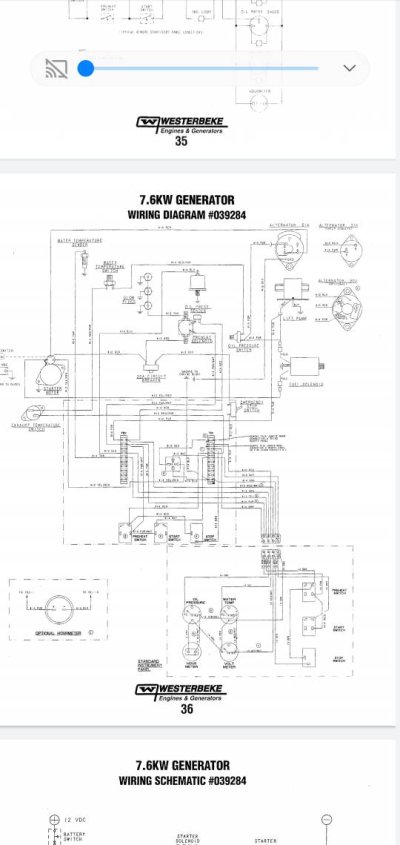
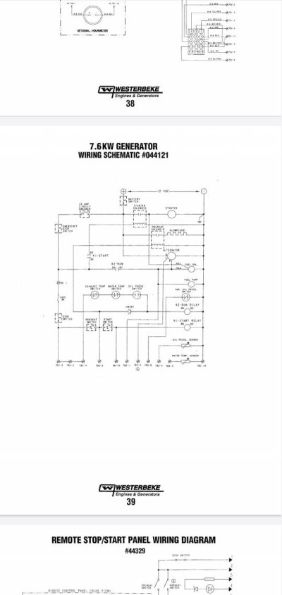
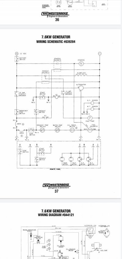
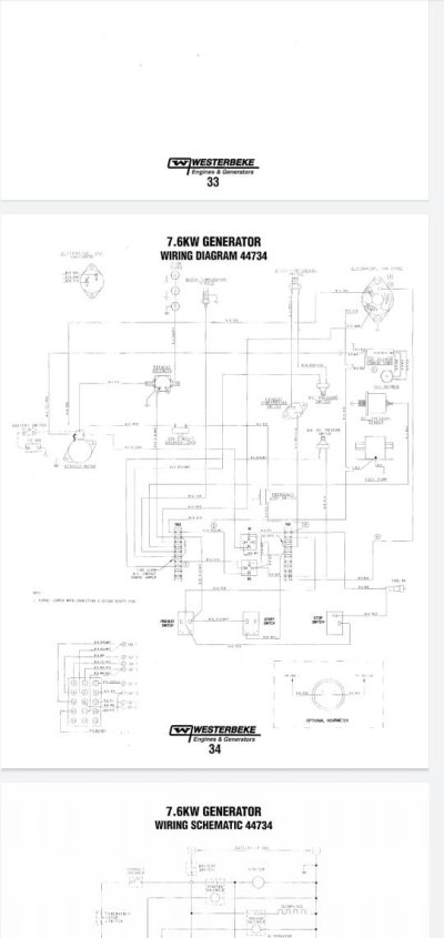
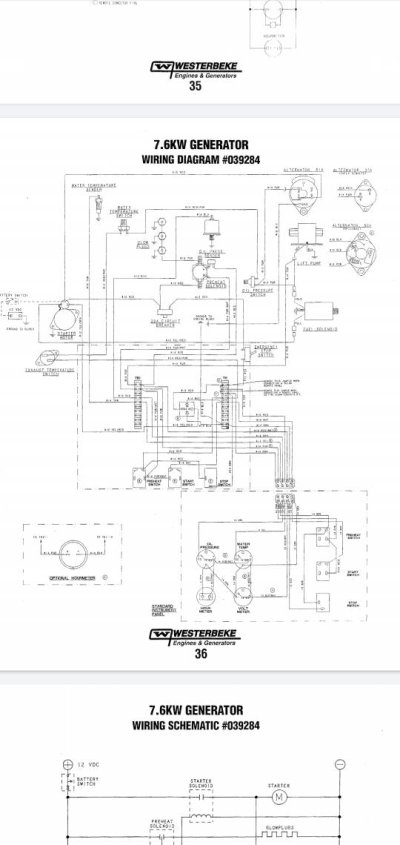
Thanks for the wiring diagram, it looks like it might be a relay. Does anybody have an idea of what auto parts store would have it and a part number or what kind of relay I should tell them I need. It looks like it’s a four pin 12 V normally open relay
twistedtree
Guru
Thanks for the wiring diagram, it looks like it might be a relay. Does anybody have an idea of what auto parts store would have it and a part number or what kind of relay I should tell them I need. It looks like it’s a four pin 12 V normally open relay
I think any of the big outfits would have one. I'd ask for a "cube relay", and have a picture on your phone to show them.
There appear to be two types with either a single pole or double pole relay. You only need a single pole, but a double pole would be fine and just leave you with an unused terminal.
SailorGreg
Senior Member
I think any of the big outfits would have one. I'd ask for a "cube relay", and have a picture on your phone to show them.
There appear to be two types with either a single pole or double pole relay. You only need a single pole, but a double pole would be fine and just leave you with an unused terminal.
Have you looked at what conditions need to be met for that relay to switch? My guess would be the shut down circuit is preventing the relay from passing current.
All of the auto shut down circuits work the fuel solenoid, and if any of the shut down circuits are not meeting conditions, then the fuel solenoid will not activate.
Your schematics are a bit too hard for me to read, but before I would replace relays, I would work back through the logic of the relay and see if the conditions are being met.
When you hit the glow plug switch it bypasses the shut down circuit, specifically low oil pressure.
Anyway, lack of current on the other pole of the relay could mean it is, or is not, seeing voltage from one of the shut down circuits.
mike66
Guru
These might be clearer
https://www.westerbeke.com/category/5.7BTD-50Hz/5399ADA2DAF73A26740BF6EA#techdocs.
https://www.westerbeke.com/category/5.7BTD-50Hz/5399ADA2DAF73A26740BF6EA#techdocs.
twistedtree
Guru
Have you looked at what conditions need to be met for that relay to switch? My guess would be the shut down circuit is preventing the relay from passing current.
All of the auto shut down circuits work the fuel solenoid, and if any of the shut down circuits are not meeting conditions, then the fuel solenoid will not activate.
Your schematics are a bit too hard for me to read, but before I would replace relays, I would work back through the logic of the relay and see if the conditions are being met.
When you hit the glow plug switch it bypasses the shut down circuit, specifically low oil pressure.
Anyway, lack of current on the other pole of the relay could mean it is, or is not, seeing voltage from one of the shut down circuits.
I believe he confirmed that the signal to activate the relay was present. The pre-heat also bypasses all the safety switches so is should still start even with a bad switch. It just wouldn't keep running after you release the pre-heat.
mike66
Guru
Did you try turning over the starter at that point to see if she fires up?Wondering if I might have a bad relay. I’m getting voltage to the red wire but no voltage to the red and white wire. However if I jump and apply voltage to the red and white wire ithe lift pump comes on. Am I to assume that’s a bad relay. Or could it be something with the other switches down stream.
fgarriso
Guru
You might try manually holding back the " fuel arm " that the solenoid is attached to. You must hold it back firmly to work. The "kerchunk" that is herd when holding the preheat switch is the solenoid pulling in and the fuel arm locking in place. 

fgarriso
Guru
Both of the water over temp shutdown switches are ( normally closed ). Just take a ohm meter and check them.
Engine Circuit Breaker
The generator's engine is protected by an engine mounted
manual reset circuit breaker (20 amps DC). Excessive current
draw or electrical overload anywhere in the instrument panel
wiring or engine wiring will cause the breaker to trip. In this
event the generator will shut down because the opened
breaker interrupts the DC circuit. If this should occur, check
and repair the source of the problem. After repairing the
fault, reset the breaker and restart the generator.
FUEL RUN SOLENOID
The fuel run solenoid is mounted in a threaded hole on the
engine's block just aft of and below the engine's fuel injection pump. Proceed as follows when installing a replacement
or new fuel run solenoid.
1. Visual access to the fuel injection pump's fuel rack is
needed. To obtain this, remove tI1e small square side
cover and gasket just below the fuel injection pump.
2. Thread the locknut onto the solenoid and then apply a
small amount of Teflon sealant to the threads on the
solenoid.
3. Thread the solenoid into the hole on tile engine and
observe the solenoid plunger through the cover opening.
Allow the plunger to contact the fuel rack and move fully
into the injection pump. Do not thread further so as to
push the plunger into the solenoid.
4. Back the solenoid out 1/4 - 1/2 of a turn and secure it in
position with the locknut.
Locknut Torque Value 28,9 - 36.2 fHb (4.0 - 5.0 m-kg)
5. Properly connect the tlu'ee electrical leads from the solenoid. Two of the connections plug into the engine harness
and the third grounds to the engine block at an adjacent
inboard threaded hole with an 8mm bolt.
6. Reassemble the cover and gasket and test run the unit. Make
certain that the unit stops when the solenoid is de-energized.
fgarriso
Guru
The following troubleshooting table describes certain problems
relating to engine service, the probable causes of these problems. and the recommendations to overcome these problems.
Problem Probable Cause
PREHEAT switch depressed: 1. Battery Switch not on.
no panel indications;
fuel solenoid or electrical fuel pump 2. Emergency stop switch oft
3. 20-Amp circuit breaker tripped.
4. K2 relay
5. Loose battery connections.
START SWITCH DEPRESSED, no starter 1. Connection to solenoid faulty.
engagement.
2. Faulty switch.
3. Faulty solenoid.
4. Loose battery connections.
5. Low battery.
6. K1 relay.
Note: The engine s electrical systenl is protected by a 20 amp
manual reset circuit breaker located on a bracket at the rear
of the engine.
Verification/Remedy
1. Check switch and/or battery connections.
2. Check emergency stop switch position.
3. Reset breaker; if breaker trips again, check preheat solenoid
circuit and check circuit for shorts to ground.
4. Check K2 relay.
5. Check (+) connection to starter solenoid and (-) connection to
engine ground stud. Check battery cable connections.
1. Check connection.
2. Check switch with ohmmeter.
3. Check that 12 volts are present at the solenoid connection.
4. Check battery connections.
5. Check battery charge state.
6. Check K1 relay.
START switch is depressed; panel 1. Poor connections to fuel solenoid. 1. Check connections.
indications OK; starter solenoid OK
fuel solenoid not functioning. 2. Defective fuel solenoid. 2. Check that 12 volts are present at the (+) connection on the
fuel run solenoid.
Generator engine cranks, but does not 1. Faulty fueling system. 1. Check that fuel valves are open.
start, fuel solenoid energized. 1 a. Switch to combine vehicle and start batteries.
1 b. Replace batteries.
1e. Check fuel lift pump.
1 d. Change inlet fuel filter.
2. Preheat solenoid faulty. 2. Check solenoid.
Engine can't be stopped. 1. Faulty DC alternator. 1. Remove Exc. connection at alternator, repair alternator
fgarriso
Guru
GLOW PLUGS
An accurate way to test glow plugs is with an ohm meter.
Touch 'one prod to the glow plug's wire connection, and the
other to the body of the glow plug. A good glow
plug will have a 1.0 - 1.5 ohm) resistance. This method can be
used with the plug in or out of the engine .
An accurate way to test glow plugs is with an ohm meter.
Touch 'one prod to the glow plug's wire connection, and the
other to the body of the glow plug. A good glow
plug will have a 1.0 - 1.5 ohm) resistance. This method can be
used with the plug in or out of the engine .
twistedtree
Guru
I think we need to go back to the symptoms. The schematics help, but I am seeing two versions that are different, so I'm not sure which matches the genset in questions. Regardless, the symptoms are
1) When you engage the preheat switch, there is no clicking of relays or fuel solenoids.
2) When you further engage the start button, the engine cranks but does not start.
With this, and using either schematic, it tells us:
1) The control breaker is on and supplying power. If it weren't, the engine wouldn't crank.
2) The problem is NOT one of the safety switches, or at least they are not the immediate problem. They are bypassed when you hit the preheat switch, and the relay/solenoid should click regardless of the safety switch status.
3) The problem isn't the preheat switch itself. The same problem exists at both panels with different switches, and the pre-heat switch supplies power to the start switch, and the start switch does what it's supposed to do. So it's getting power.
So what's left is the relay or a wiring failure between the preheat switch and the relay. The OP tested the relay, but I'm not 100% clear on what was checked. But I think he confirmed that the preheat signal was reaching the relay, but the relay wasn't energizing. Now that still leaves some wiring failure possibilities like the relay coil ground, but is most likely the relay. There is a second relay shown in one of the pictures, so a simple and conclusive test would be the swap the relays and see if the problem follows the relay. I don't think he tried that, but instead elected to just get a new relay.
mike66
Guru
Correct. I suggested the relay swap, didn't hear any results. Also, bypassing the k2 relay by shorting the ? Red wires from terminals 30 and eighty seven together a should activate the fuel system (pump and solenoid).
Then the gen should crank and run.
Then the gen should crank and run.
fgarriso
Guru
I suggested manually moving the fuel solenoid and the throttle arm .
I know this works because I have had the same problem on the same generator.
When you hit the preheat switch you should have 12vdc on the solenoid then here a kerchunk from the solenoid AND the throttle arm.
The 20amp breaker can be removed from the circuit as it only goes to the chamber preheaters.
The fuel solenoid is a common failure item. If it doesn't work the fuel arm will stay on the engine stop mode.
fgarriso
Guru
Jumping the purple and red wires should bypass relay K2
Everyone is getting to tied up on what color wires they have. What they need to focus on is what color the electrons are and what color they change to when going from negative to positive terminal.

The flow of electrons is termed electron current. Electrons flow from the negative terminal to the positive.


Dkk3000
Veteran Member
Sorry, I’ve been out of town and just got back. I did buy a new relay and the same problem exist, and I’m going to put the other relay on the other relay in the picture. I’m also going to jump 87 and 30 and see if I can’t get the fuel solenoid to start.
Simi 60
Guru
- Joined
- Jul 1, 2016
- Messages
- 5,482
- Location
- Australia
- Vessel Make
- Milkraft 60 converted timber prawn trawler
I think we need to go back to the symptoms. The schematics help, but I am seeing two versions that are different, so I'm not sure which matches the genset in questions. Regardless, the symptoms are
1) When you engage the preheat switch, there is no clicking of relays or fuel solenoids.
2) When you further engage the start button, the engine cranks but does not start.
With this, and using either schematic, it tells us:
1) The control breaker is on and supplying power. If it weren't, the engine wouldn't crank.
2) The problem is NOT one of the safety switches, or at least they are not the immediate problem. They are bypassed when you hit the preheat switch, and the relay/solenoid should click regardless of the safety switch status.
3) The problem isn't the preheat switch itself. The same problem exists at both panels with different switches, and the pre-heat switch supplies power to the start switch, and the start switch does what it's supposed to do. So it's getting power.
So what's left is the relay or a wiring failure between the preheat switch and the relay. The OP tested the relay, but I'm not 100% clear on what was checked. But I think he confirmed that the preheat signal was reaching the relay, but the relay wasn't energizing. Now that still leaves some wiring failure possibilities like the relay coil ground, but is most likely the relay. There is a second relay shown in one of the pictures, so a simple and conclusive test would be the swap the relays and see if the problem follows the relay. I don't think he tried that, but instead elected to just get a new relay.
Yep, and this is all looking more and more like my 4 year issue mentioned here.
And a workaround that I use to make genset run.
https://www.trawlerforum.com/forums/showpost.php?p=955345&postcount=29
I to have swapped out relays with no joy so its gotta be a wire "somewhere" in ours
STB
Guru
What is the exact model of your generator? I want to see if I can find a schematic.
Dkk3000
Veteran Member
The history to it, is that the generator overheated and shut itself down. The last time this happened I had to put a new water temperature switch in. But it appears that that is not the same problem now
STB
Guru
Dkk,
I sent you a PM. Give me a call, if you'd like.
Cheers!
-Greg
I sent you a PM. Give me a call, if you'd like.
Cheers!
-Greg
Barking Sands
Guru
- Joined
- Dec 24, 2019
- Messages
- 888
- Location
- United States
- Vessel Name
- M/V Intrigue
- Vessel Make
- 1985 Tung Hwa Senator
No I saw that switch and it was actually on
If you have access to that switch pull the terminals off gently and check resistance over that switch with it in the closed and open position. If you cant access it cycle the switch many times back and forth to see if you can possibly knock off some corrosion and try again. That switch will cause that issue. You have checked many other items and they seem good. But other than confirming that switch is in the correct position you haven't assessed it for serviceability.
For some reason on mine (4.4) it will occasionally move to the other position from vibration. I crank it and start troubleshooting and then remember that damn switch. I usually just put it in the opposite of whatever position its in and try it again and it starts right up. I think i am going to move it to a better location and label it better.
But you might want to rule that switch out. Ideally you want to not even breathe on it...and gently pull the wires off and put you meter in ohms and read the ohms through the switch. One probe on each switch terminal. You want to see .1 or .2. If you get a reading like 4k or some very high reading then that is likely the issue.
***edit*** Im off Monday and going to my boat in Tarpon Springs to do some work. I may be able to stop by if you still dont have it fixed. Your about 25 min south of Tarpon it looks like.
Last edited:

