An isolation transformer is normally wired so that no current path from shore continues to the boat's wiring.
Normally the shore hot (black) runs through the primary coil of the transformer and returns via the neutral (white) completing the circuit.
The shore grounding conductor (green) is tied to neutral back at the main and is basically a parallel safety neutral to keep a metal chassis from becoming hot if wiring goes bad. I'll come back to this in a minute.
The boat power is electromagnetically (inductively) coupled to the shore power via another coil, called the secondary coil, placed next to the primary coil in the transformer box. Just like the primary, it has a black connected to one end, which, in this case, will serve as the boat's hot. And, just like the primary, it has a white connected to the other end, which, in this case, will serve as the boat's neutral. As loads are connected between the black and the white on the boat side, they complete the circuit.
As alternating current from shore power passes through the primary coil, like an electromagnet, the current generates a perpendicular magnetic force. It is this magnetic force that, because it is changing, produces the flux that can drive current flow in the 2ndary circuit.in this way there are two different circuits, one including the primary qinding and one including the secondary winding. These circuits each have electrical current flow, and the primary is driving the secondary -- but through a magnetic (inductive) coupling vs an electrical coupling.
Since the transformer is the source of current for the boat, the grounding conductor on the boat is tied to the white wire on the boat. In this way if a hot wire chaffes and touches exposed metal, it'll shirt and pop an on-board breaker or fuse rather than being a shock hazard for a human.
The transformer, itself, us in a metal case. Thus case could become energized by a chuffed shore hot wire or by a chaffed boat hot wire. Bht, UT can only be protected from one or the other by connecting UT to either the shore grounding conductor or the boat grounding conductor. Since the greater risk is from the boat's wiring as it is more prevelant on the boat, that is the one it is tied to.
What then happens with the shore grounding conductor? It is either not connected to anything or, more commonly is connects to an electrostatic shield (not to be confused with the chassis, which is the outside metal tied to the boat's grounding conductor and neutral). This shield is just a piece of foil between the two coils that prevents a certain type of capacitive electrical noise that can result from having two energized blobs of metal nearby.
The upshot is that I'm not seeing how the 1v measured between neutral and ground on the boat can be related to the 1v between neutral and ground on the shore side.
....but this email is full of assumptions.
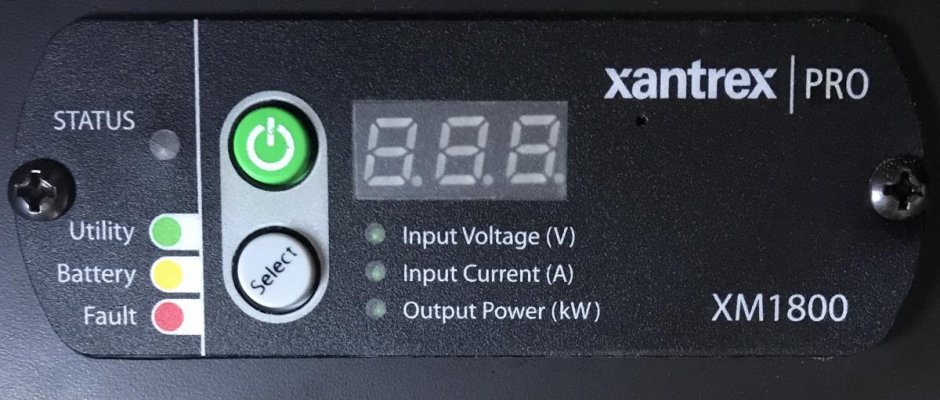
One question might be, if you unplug shore power and let your inverter supply the boat...is the 1v still present? If so, you know it isn't coming from shore!
The control bits of most inverters are powered off of the 12v circuit. As a result, I am unsurlrised that it seems off, disabled, and shutdown without 12v.
One thing you can do is to look at your Premarin charger. Shut down all of the loads except Keith's and the inverter (just briefly) and look at the current it is supplying to the battery. Microwave a cup of qater and see if it jumps up a lot. Stop the microwave and see if it settles back down in a few minutes after replenishing the batteries. When it does repeat the experiment. If you see the current jump, do it 2, 3, or 4 times to convince yourself.
If the current goes up a lot tgen the microwave comes on, even though correlation isn't necessarily causation, it'll be a good bet it is supplying the microwave. If you can run the microwave for a few minutes and the charger doesn't start working hard, good bet the inverter isn't inverting 12vdc into 120vac
") )
)