12V breaker panel LED indicator light replacement

The friendliest place on the web for anyone who enjoys boating.
If you have answers, please help by responding to the unanswered posts.

PocketAces

Veteran Member
Joined
Dec 25, 2019
Messages
45
Location
Canada
Vessel Name
Pocket Aces
Vessel Make
Mainship 34T '08
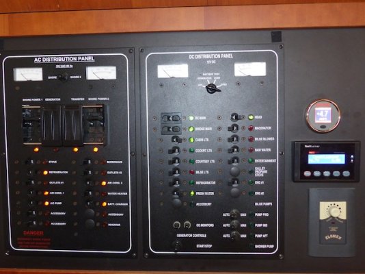
Hi, I have a 34T '08 and most of the LED lights on the 12V breaker anel (and some on the 120V breaker panel as well) have died. On the old Yahoo groups there were several posts on this topic, but alas, Yahoo groups is no more...

A few questions:
* Where to get the replacement LEDs and what type?
* How to get the old ones out. They are locked in place with a small metal plate which was pushed on to prevent them popping out. Due to tricky access with all the other wires, it is tricky to remove these. Can I just pull the LED out the front? (Seems to me they will break)
* Wiring. To remove the existing ring connectors is also a challenge to me. Not sure I can even get a screw driver in without dismantling a whole lot. Is it reasonable to cut the existing wires and re-connect with a bunch more butt connectors? I think a boat electrician might roll his eyes at the addition of 20 or so extra connectors?
Are there any other tricks such as removing each breaker switch first or calling a qualified electrician?
Thanks
 
Don’t know if they will fit your panel but Blue Seas have panel LEDs. Look on their website and click on Products then Panels and then Panel Accessories.
 
LED voltage

Be sure not to use 12V LEDs, your charging system is over 14V. 12V LEDs will burn out again.
 
Are you sure they are LEDs? On my 06 34T they were incandescents. I wound up changing the 12v side of the panel to LEDs.

I ask because the incandescents are notorious for burning out; LEDs not so. I made the change 5-6 years ago and so don't remember the source - might have been Mouser.

Mine came out from the front. I didn't have any locking plates behind the panel.

Rather than chasing the ring terminals I just pulled the old light out the front, cut the wires, crimped the new legs to the exposed wires, and pushed the new fixture into place.

I felt no need for an electrician in this process.

During this I changed some of the 12v (should be 14v as previously noted) from green to red. My system was: Green are fine to be left on all the time (cabin lights, refrigerator, head, etc) and Red should be on only when needed (ER lights, macerator, etc). Seeing a red light on was a good reminder I had forgotten to turn something off.
 

Attachments

  • P1030378.jpeg
    P1030378.jpeg
    92.4 KB · Views: 58
Last edited:
First, search the internet for LED panel lights. There are many styles and sizes out there.

Second, for older incandescent panels lights, if you can not find a panel light large enough to fill the hole. Just plug the hole with a wooden dowel. Use a sharpie to color it black, drill the correct size hole and insert the new panel light.

Third, make sure you need these lights. I spent a whole lot of time replacing panel lights in my last boat only to find that the light kept we awake at night.
 
PocketAces, if the dead LED's are always on (24/7/365) then they have exceeded
100,000 hours and could be expected to need replacement due to age alone.
If they are only occasionally lit then I would search for the reason they burned out.
If they are actually incandescent then you have your answer and should be easily accessible.
LED's will typically last 50,000 hours if properly installed.
Make sure the ground to the LED's has not failed in some way, too.
 
The panel lights in our 2003 Mainship are not LED's. They are Sierra 12 volt indicator lights. They push in from the front. I have replaced most of them. I have not had to replace any of the 120 volt lights yet.
 
Thanks folks for the very useful feedback!
danderer: I really like the idea of red vs green for normal vs occasional use. And if you are okay with cutting and crimping the wires, then I believe that should be good enough. (A bit more messy, but not less functional or safe). Regarding LED or Incandescent, I have just assumed they were LEDs, but the could very well be incandescent. I have been pretty good about switching off all breakers on the DC side except Bridge main and Refrigerator (for both fridges) so most of them should be well within the LED limit (but not incandescent)

tiltrider1: The AC and DC panels are behind doors, so no problem about keeping me awake!

So that leaves the question of how to get them out due to the backing plates. I will use the one on the Engine 2 (not used) as a guinea pig and pull hard enough from the front until the light either breaks or comes out. (I suspect it will break as the backing plates seem quite effective and very inaccessible)

A project for a cold rainy winter here in Vancouver BC
 
I actually found the info for the LEDs I used. They were purchased through a company named Spemco, though they were manufactured by Solico.

I only did the 12v side; I never had any of the original 120v lights fail.
 

Attachments

  • Screen Shot 2021-01-04 at 6.16.39 AM.jpg
    Screen Shot 2021-01-04 at 6.16.39 AM.jpg
    21.8 KB · Views: 53
danderer: Thanks for the info about Solico. I will get some and see how they fit/look.
 
I found LED replacement lights with a company called Pacer Group. Purchased thru their website.
1555 Apex Rd, Sarasota, FL 34240
Here is the model number for green; “E3L-14-G
LIGHT, INCANDESCENT 14V GREEN 5/16" MOUNT w/CLIP”
My existing incandescent lights had a locking clip. Once I removed the clip, I pulled out the existing light and cut the two wires.
Unfortunately my wire butt connectors would not fit back through the hole from the front. I had to connect the wire connections from the rear of the panel.
Even though the new LED’s came with the locking clips I did not install them. It was too difficult to slip them back on.
Pacer was the supplier to Mainship for most / all of their electrical gear.
How about replacing from front by sliding a piece of appropriate size shrink tube over wires, twisting wire, solder and shrink the tubing?
Should fit back thru hole?
I do believe ABYC excludes small AWG wires from the no solder only connections. Maybe twist qualifies as "mechanical"?
 
I was hoping that your idea on soldering the wires would suffice. It’s a pain to connect the wires behind the panel.
Unfortunately I found information regarding soldering; Per ABYC (E-11.16.3.7), “Solder shall not be the sole means of mechanical connection in any circuit”. Further, crimping provides a solid mechanical connection resistant to “cold joints” breaking under fatigue, and removes strain.
 
“Solder shall not be the sole means of mechanical connection in any circuit”.

I came across this when doing some recent electrical with big lugs. I thought that soldering the cables would provide more surface area and less resistance, and it probably does. Problem is that some soft solders can melt at 350F and then the wire flops out because no crimp. Not good to have dangling hot wires. So I soldered and crimped.

I have a green DC indicator light on the panel. I've been contemplating moving/removing it and putting a red LED indicator light above the entire panel and shining down on it. That way it would serve as both an indication that the panel is hot and a night light for the panel so that no cabin lights or a flashlight is required to check what's on/off at night.

I've installed 12V LED singles in various boat applications and never had a problem when charging at a voltage of 14.7. It could be that vendors who sell 12V LED lights realize that they will likely be used on vehicles and boats that will exceed 12V a little. I mistakenly put in a 4V LED on one project and it disappeared in a tiny puff of smoke, so voltage is important, but maybe there is a certain amount of leeway.
 
I was hoping that your idea on soldering the wires would suffice. It’s a pain to connect the wires behind the panel.
Unfortunately I found information regarding soldering; Per ABYC (E-11.16.3.7), “Solder shall not be the sole means of mechanical connection in any circuit”. Further, crimping provides a solid mechanical connection resistant to “cold joints” breaking under fatigue, and removes strain.
I believe ABYC also states someplace that 16 AWG is a min size.
My recollection is there is an allowed exception for both.
I'll bet your VHF radio or Mike has some soldered connections?
I will try to look it up... will report back if I find anything.
 
I get stuff like that from mpja.com Great company to deal with and they have a whole load of replacement electronics suitable for boats...
 
I've found these folks to be very helpful with panel items.
The LED's I used from them were simple push-in.
See their website.

COMMON GROUND MARINE INC.
888 PRODUCTION PLACE NEWPORT BEACH, CA 92663
 
Thanks folks for all the suggestions. I am sure I can now get replacements okay.
Regarding the other issue of how to get the old ones out. The AC panel can simply be pulled out the front as others have mentioned. But the DC ones have a backing plate making it impossible to pull out the front. But I figured out a simple solution. Since the light is dead anyway, there is no harm in destroying it. So when I get to doing the job, I will simply crush the head with pliers and pull them out the back. Should work. Then re-wire as per previous suggestions on this thread.
 
danderer: Thanks for the info about Solico. I will get some and see how they fit/look.

How did these work out for you? Need to replace some on my panel as well.
 
How did these work out for you? Need to replace some on my panel as well.

Looks like PocketAces has been inactive since May.

Bacchus, I see you listed the same make/model replacement LEDs in the very helpful parts list you created and shared.
Did these fit your existing light holes? Did they work well for you?
 
Looks like PocketAces has been inactive since May.

Bacchus, I see you listed the same make/model replacement LEDs in the very helpful parts list you created and shared.
Did these fit your existing light holes? Did they work well for you?
I have replaced a few of mine but honestly can't confirm the part #.
The ones I had on hand were given to me by a friend that got out of boating.
My guess is if I posted a number it was accurate at the time of posting.
The ones I replaced worked fine. I do have some additional ones that need replacement so will need to measure and fi d the correct ones again.
When I questioned my brother about ABYC wire size exclusion he confirmed there was an exception for "instrumentation". He also sent me some very small dia crimps for fine wire that should fit through the hole allowing replacement from the front of the panel.
 
I was hoping that your idea on soldering the wires would suffice. It’s a pain to connect the wires behind the panel.
Unfortunately I found information regarding soldering; Per ABYC (E-11.16.3.7), “Solder shall not be the sole means of mechanical connection in any circuit”. Further, crimping provides a solid mechanical connection resistant to “cold joints” breaking under fatigue, and removes strain.

So you are saying crimp but don't solder or is it ok to crimp then solder, or solder then crimp? In a lifetime of woking on various electrical and electronic equipment, I don't know that I've seen a well-soldered connection fail, but have seen crimp connections fail, although maybe those were not properly crimped. I find it hard to tell how well-secured a crimp connection is.
 
Bob
Rod / CMS "Marine How To" website has a great article on terminations including a section regarding soldering (or more accurately avoid soldering)

https://marinehowto.com/marine-wire-termination/

An excerpt from his article:
"This discussion has been beat around the net more than a tennis ball. I think the best statement on soldering a crimped terminal comes from the Senior Product Engineer Tom Michielutti at AMP.

AMP is one of the most widely respected suppliers of crimp terminations to the US Aerospace and military sectors. Below is the statement from the senior engineer at AMP. These are NOT MY WORDS.

Begin Quote:

“Subject: Soldering Crimped Connections & Solder in Crimps
This subject is discussed in AMP’s internal “Fundamentals of Connector Design” course.
Soldering Crimped Connections
In the minds of some customers, fortunately a diminishing minority, the reliability of crimped connections can be improved by soldering. In fact, soldering can degrade the performance of properly crimped connections. Such degradation can arise from the effects of soldering temperatures, the potential corrosion from improper cleaning of soldering fluxes and the effects of solder wicking on the conductors. Solder wicking causes the multi-strand conductors, which have high flexibility and stability against vibration, to become, effectively, solid which degrades both the performance characteristics mentioned. For these reasons, soldering of crimped connections is not recommended.
Should Solder be Used in Crimps?
Crimps are designed to work without solder or solder-dipped wires. Solder present in a crimp changes the deformation, metal flow, cleaning, welding, and residual force characteristics designed into the crimp.
Soldering would be an additional heat producing assembly step. Test results show that soldering or solder-dipping wires before crimping does not produce a termination superior to that obtained in a properly applied crimped termination. Some tests specifically show detrimental effects due to soldering or solder-dipping (e.g. soldered crimp terminations can lose some ability to withstand vibrations and flexing, due to solder embrittlement of the copper wire, and/or due to solder wicking up the strand of stranded wire to form a short length of solid conductor near the termination).
The terminated conductor then does not have the flexure strength characteristic of strand wire, and should behave more like solid wire which fails quickly in flexure testing.”
The above is a direct quote from AMP/Tyco/TE Connectivity. "


Also included:
"It should be noted that the NASA, Military and Aerospace wiring standards specifically prohibit crimping terminals to solid conductor wire or to solder-tinned wire. Crimps must be made first…

This is NASA’s take on soldering solder-tinned wire:

“NASA 4.3.4 Crimping – Stranded wire shall be used for crimping (Requirement). Crimping of solid wire is prohibited. Crimping of solder tinned wire is prohibited.”
“Solder tinned” wire is different than tinned STRANDING where each individual strand is tinned. Solder tinned means you pre-tinned the end of the wire before you made a crimp. Please do not do this.

If you insist on soldering your crimped terminations the the quasi-optimal way to do this (really there is no optimal way because you don’t need to solder crimped terminals) is to crimp first then solder.

As can be seen with the right tools and technique you can solder the end of the terminal and not melt the insulator or wire. You won’t achieve this with a $5.00 Radio Shack soldering iron."


I see many challenge this thinking citing anecdotal evidence or very special industries, conditions, etc that permit soldering using very controlled equipment, procedures & components that are not apples to apples when comparing the avg boater / DIY'er. Obviously everyone gets to make their own decisions but mine is to use quality crimps & crimp tools as Rod shows produce exceptionally good crimps that exceed the meager ABYC tensile requirements and cold form strands to eliminate voids for corrosion to be a consideration.
 
Thanks Don. I don't dispute any of this. But what I think is important is "properly crimped" connections. I have a lot of work experience including military and aerospace electronics and fully agree that a properly crimped connection using the proper terminal and matching crimping tool are very reliable. That said, I would bet that most DIY mechanics are not trained or do not go to the trouble of properly matching the terminal to the wire and the tool to the terminal. Sometimes maybe just a squeeze with a pair of pliers. Therefore, anecdotedly, I might propose that an amature solder connection is more reliable than an amature crimp connection.
 
Bob
I understand and agree with your point re amateur quality crimps not measuring up to well done ones.
My guess would be that an amateur that doesn't do any investigation re quality connections would do equally poor job whether solder or crimp... no or improper conductor cleaning, flux, cheap pre filled solder connectors, over kill w solder leading to essentially solid wires, poor insulation or support, successeptible to stress cracking all potential problems for those that are careless.
No data and only gut reaction.
So much depends on individual situation so I am reluctant to generalize but do understand the arguments both ways.

We are on the same page and as you know there is another thread on this particular topic. My point is that I think it's easier to make a good solder connection with minimal skills and tools. Crimps, to be done correctly, require the correct connector and the matching correct tool. I don't know that everyone knows that or bothers to ensure that. Sure, soldering requires some basic skills and process, but it's pretty universal from one connection to the next and you don't have to do much differently just because your wire gauge changed a couple numbers. That's not the case with proper crimping.

That said, because I know all this and not despite it, in my own project, I would more likely trust a good solder connection I made, including the mechaincal joining of wires and shrink wrap, over crimping because I know I may not have the correct crimp connectors and tools handy. BTW, there are ways to connect 2 wires prior to solder other than just a quick twist. We had to practice these in tech school.
 
Last edited:
Back
Top Bottom