Codger2
Guru
- Joined
- Oct 11, 2007
- Messages
- 6,691
- Location
- US
- Vessel Name
- Circuit Breaker
- Vessel Make
- 2021..22' Duffy Cuddy cabin
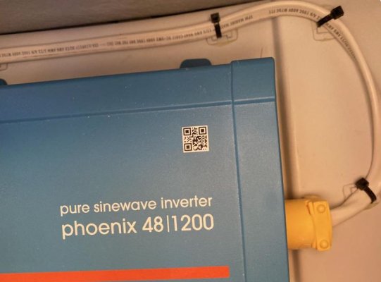
My Duffy/Cuddy Cabin is now one week old and I am finished with trying to understand Duffy's thinking when it comes to the installation of the inverter. (example) My boat has 4- I20-30amp receptacles of which only one is hot when on shore power. The other 3 are hot only when the inverter is switched to on. My previous experience with the last 5 boats was that all circuits were hot when on shore power and only those designated were hot when on the inverter. This means that should I desire to plug a 120v appliance into one of the 3 outlets in question while in the slip, I must have the inverter on.?????