Steering Bracket questioon

The friendliest place on the web for anyone who enjoys boating.
If you have answers, please help by responding to the unanswered posts.

SimonBryan

Veteran Member
Joined
Jan 17, 2016
Messages
65
Location
Australia
Vessel Name
Monesk
Vessel Make
Island Gypsy 32
Hi all
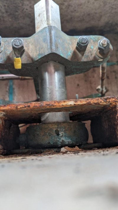
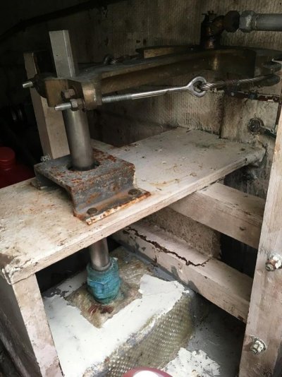
The attached image is of the bracket at the top of the rudder in the lazarette. Obvioulsy needs some attention - either replace or clean and paint. Have cleaned and applied some rust kill as a temp measure.
Would this be a part I could purchase or better/easier to get one fabricated?
Also I see how tto remove it but want to ensure I dont drop the rudder out the bottom!! It looks like the rudder is held in by the bracket around it just underneath this bracket.
Is this a job I should attempt in water or wait until it is hauled out for antifoul?
 

Attachments

  • PXL_20200913_010228062.jpg
    PXL_20200913_010228062.jpg
    82.7 KB · Views: 95
You might try some POR-15 to paint it first. They make a line of products to clean and treat the metal then paint it.
 
Comodave - yes i brushed and sanded it back to a reasonable finish and applied some Rist Guard Rust Convertor, will take down the top coat next time. But still feel it should be replaced if it is critical
 
From the photo I thought it was just surface rust, does it go deeper? If it is just surface rust I don’t see a problem with just refinishing it. However if the rust is deeper then I would replace it. If you are going to replace it then I would probably do it on the hard.
 
Yeah some of the rust was quite deep at a couple of mm.
 
Simon,

To answer your question, the rudder post is held vertically ie what stops it dropping down by the circular "donut" under the top of the bracket. The top horizontal arm is for the steering.

Looking at the bracket, it looks to be a rectangular box section - the bottom long side is what the "donut rotates on, the top long side - not sure.

Sooo, undo the donut and down drops the rudder so its an out of water clean up and repair/replace
 
Brisybiy

I think the bracket would come off without touching the donut. Bit would have to remove the steering gear clamp above so I think decision made it is an out if water repair.
Now just need to find one.
 
What is the bracket doing? I had a bracket like that, but there was no completed box section at the bottom with the donut. There were 4 bolts securing each of 4 "feet" to a wooden base. As far as I could see it did nothing and had no function,not being attached to anything. Yours may be different.
I had mine looked at by 2 people, one an ex Halvorsen shipwright who thought it was for a type of steering my boat did not have(? hydraulic, mine was chain/cable).
My fittings were badly rusted, I cut the fittings(one around each rudder stock) so I could remove it from around the stocks without disturbing anything and undid the 4 bolts. The boat continued to steer and operate normally for the next 2+ years with the brackets removed.
Just have a good look and make sure the bracket is actually doing something.
 
Brisybiy

I think the bracket would come off without touching the donut. Bit would have to remove the steering gear clamp above so I think decision made it is an out if water repair.
Now just need to find one.
 
I think the rusted bracket was where the original bearing was. Or maybe it had 2 bearings in the past. The bearing is what keeps the rudder shaft from dropping and 2 would be insurance.
 
BruceK and Lepke - as far as I can tell nothing. Hadnt thought that it might be superflious. It is bolted to a wooden frame below and as far as I can tell nothing else
 
No idea what the bracket is for. Early Willards used a different type of hydraulic steering ram (Wagner T-Ram) that encircled the shaft vs attach to a rudder arm. But shaft was keyed, not squared; and probably just a north American thing since the steering systems were PNW based (the larger T-Ram systems are still built). My best guess is this bracket was some sort of spacer.

To answer the original OP question, brackets like these were fabricated one-off pieces even when the boat was originally built. There would be no source for a replacement even if this boat were 6-months old. Getting replacement parts from builders is usually extremely difficult and expensive even for current model boats. Bears no resemblance to dealer networks in automotive industry.

Peter
 
Clean it and paint it.


Nobody going to say anything about the empty bonding connection?
 
Clean it and paint it.


Nobody going to say anything about the empty bonding connection?
I actually noted the bonding connection. Didn't say much as it wasn't part of the exam question.

Im redoing my bonding system as we speak. Had teeny solid core wires - probably #12 or so. Going with #8 tinned/stranded.
 
Clean it and paint it.


Nobody going to say anything about the empty bonding connection?


Do you mean the earth strap, as far as I remember it is in good shape, have you spotted a problem?
 
Do you mean the earth strap, as far as I remember it is in good shape, have you spotted a problem?

It appears in the photo that there is a missing bonding wire on the left side in the photo.

I have been redoing my bonding system. I did the port side last winter when I had that engine out. This winter is the starboard side since the starboard engine is coming out this winter. It is amazing how many connections there are in the system.

See what you mean but I believe it is a black wire bent back, but will definitley recheck. Thanks for the headsup
 
Here the bonding system is green wire, maybe down under they are black???
 
It is identical to my IG. The top is welded to 2 pieces of angle iron if I remember correctly. Any machine shop could fabricate the piece. Quadrant would obviously have to come off for replacement. Upper bearing would not be touched. Mine are lightly rusted. I took a wire brush to them once but haven't touched them otherwise. Lazarette is my damp dungeon where anything that doesn't have a reserved place gets tossed and forgotten.

(IG's used flat cu strip for bonding, not wires.)
 

Attachments

  • IMG_7257.jpg
    IMG_7257.jpg
    84.3 KB · Views: 30
Last edited:
It is identical to my IG. The top is welded to 2 pieces of angle iron if I remember correctly. Any machine shop could fabricate the piece. Quadrant would obviously have to come off for replacement. Upper bearing would not be touched. Mine are lightly rusted. I took a wire brush to them once but haven't touched them otherwise. Lazarette is my damp dungeon where anything that doesn't have a reserved place gets tossed and forgotten..
That square piece of metal bolted to wood by 4 bolts and surrounding the shaft, looks like what my IG36 had around each shaft. What is it doing? One theory was a retainer preventing excess movement in the event of rudder strike. I can`t see if there is something functional relating to the shaft located underneath the metal plate, so it might be doing something.
 
That square piece of metal bolted to wood by 4 bolts and surrounding the shaft, looks like what my IG36 had around each shaft. What is it doing? One theory was a retainer preventing excess movement in the event of rudder strike. I can`t see if there is something functional relating to the shaft located underneath the metal plate, so it might be doing something.

As far as I can see the shaft passes through it with about 1cm clearance and nothing underneath.
 
Here the bonding system is green wire, maybe down under they are black???

The best thing about standards is there are so many to choose from! As mentioned by someone the main part of the bonding system is a copper strap. Probably need something a little more flexible for this job.
 
As far as I can see the shaft passes through it with about 1cm clearance and nothing underneath.
So it remains a puzzle. A common fitting on IGs which connects to nothing. You can`t remove it without removing the rudder, unless you cut it across and unbolt the 2 sections.
Is it adding strength to the area?
Is it intended for hydraulic steering not fitted?
Something else?
Just another sweet mystery of life?
At least my removal and continued operation of the boat pointed to no obvious negative removal consequence.
 
That is a typical rudderstock carrier and because it’s in the lazarette it’s going to rust. I wouldn’t worry about this as rust or scale always appears worse than it is. If you see deflection or movement then get it replaced but I doubt you will. Not knowing your vessel type I have to ask is this a balanced spade type rudder(s) or skeg base bearing supported single screw ? It’s late so I’m closing down for the night but look up rudder carrier for an explanation of what it does. Quite simple and necessary.
 
Garbler, thanks,I searched rudder carrier. The carriers depicted seems to involve a bearing on the rudder stock whereas the IG version does not,and stands unconnected to the rudder stock it encircles. Is it somehow still providing strength or reinforcement to the rudder and if it is, how does it do that?
 
True rudder carrier as found on commercial vessels will not be found on smaller trawler yachts. Actually the term carrier has been bastardized and used to describe a similar rudder support found in motor yachts. It’s purpose is pretty much the same which is to support the rudder assembly from falling out if no skeg and base bearing is in place and to control or stabilize the stock and tiller head against radial loads.

So I can’t see much of your set up but if that rudderport has a steel plate and what looks like a shaft collar then it’s a variation of a rudder carrier. It’s important on larger blade heavy stocked rudders. It helps to stabilize the upper or inboard portion of the stock against movement and to some degree vibrations that eventually take a toll on tiller head linkages, hydraulic seals and upper and lower bearings. It is also a key player in protecting rudderport fiberglass tubes which are common on Far East hulls. You don’t want contact between the stock and glass tube. There should be a bearing or bushing in way of the plate and a collar to prevent dropping. Better installations have split bushings/bearings for service. Attempting repairs to rudderports and carriers afloat can be ill advised. It’s been way too many years since I was agile enough to crawl a lazerette and get intimate with this equipment so I could be a bit fuzzy on the details.
 
...So I can’t see much of your set up but if that rudderport has a steel plate and what looks like a shaft collar then it’s a variation of a rudder carrier. .....
I`ve probably bothered you enough, but here`s what Simon said: "As far as I can see the shaft passes through it with about 1cm clearance and nothing underneath." If that is right (it probably is, mine was the same)ie. no shaft collar, and there is no other contact between the bracket and shaft, what is the bracket doing? I can`t see it does anything unless it`s somehow attached to or supporting the shaft. Maybe it stabilizes the area, but even that is hard to see.
 
I am wondering if, like Lepke posited, the metal bracket is/was intended for a more robust bearing system. Interesting/odd that multiple members here have the same boat with the same, apparently unused bracket.

Is it possible the metal bracket is intended to have the shaft collar located on top of it, thereby helping spread the load onto the wood shelf? Perhaps a PO changed it for some unknown reason (I know, on multiple boats the same thing happened?)

Our boat is NOT an IG, but does have a very similar constructed boxed plate that is the mount for an upper rudder bearing. We have a shaft collar too, which is above the bearing.

In looking at some online drawings of rudder stock design, there is a piece that tends to be in that area of the rudder stock, and its called the carrier but has a bearing in it in each case.

In the OP's photo, you appear to have a shaft collar under the metal bracket, and is that a large flat washer under the shaft collar? Is there a bearing in the wood shelf?

Excuse the leaked and not cleaned up grease, but here is a photo of our rudder stock / carrier assembly for reference...

At the very top of the pic (you can only see a portion of it) is the portion of the quadrant that is mounted onto the shaft. Below that is a shaft "collar" that consists of two halves that bolt onto the shaft. There is a bearing mounted into the SS plate (you can see a couple mounting screw heads.) Finally below the plate is the packing which is mounted on a reinforced fiberglass mounting area glassed onto the hull. This is a boat with hydraulic steering, BTW.

sbtd rudder upper stock gland and upper bearing.jpg
 
Last edited:
Well, I had a look at mine - sorry I didn`t get a photo. Each rudder shaft comes through the hull via the bearing and a packing gland. It then continues up about 150mm through a wooden "shelf" (12mm ply) On top of the shelf is a small plate which is bolted to the shelf. The donut, which is bolted to the shaft rotates on this small plate. Nothing else. The shaft then continues up where the steering arm is attached.

Maybe, and this is a long shot, the box section is to reinforce the plate that the donut rotates on?
 
Bruce I’m at a loss to figure out what your metal carrier shelf is doing if it lacks the bearing and shaft collar. Back in the late 70’s early 80’s a lot of trawlers were coming in from Kaohsiung as deck cargo and for a long time their drivetrain parts including shafts, rudders, props, etc. were crated up and installed by various contractors in Long Beach and Wilmington, CA. When I had my shop in San Pedro we did some commissioning work for Hans Christian and Lord Nelson and every now and then something would be missing or wrong. It would not surprise me that those carrier parts were not in the crate or just missed by the fit out crew.
 
Back
Top Bottom