jefndeb
Guru
Hello,
Odd issue here, maybe its just me...here goes.
Changing my 8E0ZD genset air filter yesterday and afterwards I was just looking around the genset area with a flashlight and I saw what looked like a pressure switch screwed into the heat exchanger manifold...upon closer look I saw only one wire was attached and I saw another wire that was not connected to anything. Hmmmmm...It was obvious that it was supposed to be connected to the other terminal of that switch but it clearly was not yet my generator still ran fine??
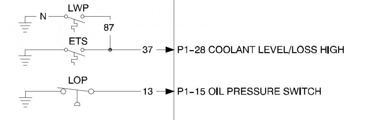
After some reading, it was found to be the LWP pressure switch (Low Water Pressure), it takes .5 PSI of impeller water pressure to close it, and it then provides a ground to P1-28 of the ADC module, however it shares that input with the ETS, (EView attachment 106852ngine Temp Sensor), which also provides an input.
Anyway..I ordered another LWP switch to be safe and today after noticing that the old one had a small leak I decided to replaced it and I connected "both" wires up this time ...but when I started the genset, it stopped after 30 seconds with a "LOC" code (Loss of Cooling) ??..I then checked with a meter and the switch closed after a slight pressure applied, so it is good..
Furthermore,.the schematic shows both sensors, LWP & ETS being tied together as they are, should provide a ground to P1-28 of the ADC module,.. under normal conditions, if either open, (no ground input) to pin 28, after 25-30 seconds, the ADC stops the genset...
My questions are--(If I am understanding this correctly so far)...
1. Why does my genset still run with the LWP wires completely disconnected?
2. Why does one section of the manual (Fault Shutdown Switches) say the ETS is "resistance" type, yet the wiring schematic shows an ETS that provides a ground to stop the genset from an when overtemp?
Comments and suggestions welcome..
Thanks...
Odd issue here, maybe its just me...here goes.
Changing my 8E0ZD genset air filter yesterday and afterwards I was just looking around the genset area with a flashlight and I saw what looked like a pressure switch screwed into the heat exchanger manifold...upon closer look I saw only one wire was attached and I saw another wire that was not connected to anything. Hmmmmm...It was obvious that it was supposed to be connected to the other terminal of that switch but it clearly was not yet my generator still ran fine??
After some reading, it was found to be the LWP pressure switch (Low Water Pressure), it takes .5 PSI of impeller water pressure to close it, and it then provides a ground to P1-28 of the ADC module, however it shares that input with the ETS, (EView attachment 106852ngine Temp Sensor), which also provides an input.
Anyway..I ordered another LWP switch to be safe and today after noticing that the old one had a small leak I decided to replaced it and I connected "both" wires up this time ...but when I started the genset, it stopped after 30 seconds with a "LOC" code (Loss of Cooling) ??..I then checked with a meter and the switch closed after a slight pressure applied, so it is good..
Furthermore,.the schematic shows both sensors, LWP & ETS being tied together as they are, should provide a ground to P1-28 of the ADC module,.. under normal conditions, if either open, (no ground input) to pin 28, after 25-30 seconds, the ADC stops the genset...
My questions are--(If I am understanding this correctly so far)...
1. Why does my genset still run with the LWP wires completely disconnected?
2. Why does one section of the manual (Fault Shutdown Switches) say the ETS is "resistance" type, yet the wiring schematic shows an ETS that provides a ground to stop the genset from an when overtemp?
Comments and suggestions welcome..
Thanks...