HELP, Inverter Install wiring

The friendliest place on the web for anyone who enjoys boating.
If you have answers, please help by responding to the unanswered posts.

SteveandZoila

Senior Member
Joined
Jan 12, 2014
Messages
150
Location
USA
Vessel Name
Miss Rita
Vessel Make
2004 Heritage East
OK guys, I need a little Help Help, Help on grasping this wiring. My boat had a separate charger and 2500watt inverter. The inverter died. The charger too small for my 1250 amp bank. New design; 2 Xantrex 2500 watt inverter chargers 130 amps each. The original set up was a relay to power some of the 120 outlets.I have probably had back feed thru this setup that have fried my new inverters over the last year,. I have had them repaired but don't want to have this problem again.


New plan: Wire one Xantrex to power all 120 outlets. Not sure how to do that. I have a pro to advise me but he will not show up!
The control panel has has a rotary switch with 6 layers equaling to 24 connections for : shore1, Shore 1&2, and Gen. Trying to diagram switch.
The Xantrex 45Has 2 inputs and 2 out puts, lots of ways to set up.
The 2nd Xantrex is going to be a back up and possible 2nd charger, really not to be considered in this question.

Sorry, pics of manuel not up yet.

OK, big question: I must avoid freeback that has fried both inverters over the last year.
I could wire the inverter into the Gen to charge 30 gauge as input, BUT would that backfeed to unit???
Output of inverter would be to ???? Output is were backfeed fries unit.
Output could be directly to one leg of Panel breakers, but when Gen is on would it back feed?
I have read many articles but am stumped. I probably need a 4 position switch Can I add another switch?
Random thought, could be the Sailor Jerry, could I change Shore 1 into inverter load?? It will not be easy, the panel wiring is very tight, it could take hours just to change one breaker. Longer to figure out wiring of rotary switch.
 
This is way beyond asking on the internet IMO. If you are having to ask, you need a pro. Find a different person, sorry.
 
Have you consulted with Xantrex? Studied the manuals? Have you read the first three chapters of Calder's "Boat Owner's Mechanical and Electrical Manual" which discuss inverter systems in detail? How about the people you bought the inverters from?

It sounds like "no" to above. I definitely agree with Comodave. If you are in Nashville or environs, the Inverter Service Center is there in White House off 65. 800-621-1271
 
Is the inverter enough to run the whole boat full time, or does it only support a limited load? There’s 2 ways to go about this depending on the answer to that question.
 
Very suprised

I have learned much from reading TF post over the last 5 years, I tell people “it's the greatest group of guys, they try to help everybody,” lots of different experiences and thoughts, I have used TF as my best
source to get opinions. I am really shocked at my replies. I was reaching out to you guys because my Pro, has not showed up for my final stage setup.

I have installed inverter/charges before and studied marine electrical systems but stump at the approach to my final stage of this one. Maybe I provided too much information and it was not clear. What I am trying to connect to the three position rotary switch, but do it properly to avoid any backfeed. In my first attempt of installing Invert/char, a few months ago; I had just turned on my genset and a relay started chattering as it fried my unit. Note the boat has a relay to supply power to a few outlets.


I took my unit in for repair/rebuild, and after discussing the problems with several fried units over the last three years, my technician suggested talking with a Pro. I also decided to rid myself of the relay and power all outlets like my old Gulfstar.


OK, I am going to tell you what I feel now, If you don have anything to contribute Don't COMMENT
BTW, I have looked at much marine info on inver/char installs, schematics, YouTube, etc. and will continue to.
Yes I have read and underline,and highlighted the Manual 2 times, and I understand everything in it, BUT it does not cover the wiring to a rotary switch. The Units are installed and wired.
BTW, I have read Calder's book thru several times, new edition. Unfortunately, I left it at home, and I would feel really stupid if I found enough info to solve this setup.
Again: I just want to eliminate any chance of backfeed to my unit.
Thank you Caphening for reply and input.

You did not answer my question, ergo I cannot advise. If you want advice we need to know the end system. Are you going to feed the boat panel 100% of the time through the inverter switching? If yes then you feed the Generator and Shore Power into a positive disconnect switching system. Some rotaries are not positive disconnect and can momentarily feed from both. From the switching system out you feed A/C In, and AC out goes to the panel, and DC goes to the batteries.

If the Inverter can only feed a limited amount 0f the boat and you need generator or shore power to power everything, then you need to split your electric panel into 2 busses, one that the inverter can cope with, and one for everything else. At that point you want a second out from the rotary switch to feed the ‘every thing else’ bus, and leave the other bus run on the inverter system.
 
You will be well served to hire experienced marine electrician. ABYC cert.
 
OK, thank you, let me collect my thoughts, I am planning to spend Sunday just investigating rotary switch connections and possible routing.
 
I have learned much from reading TF post over the last 5 years, I tell people “it's the greatest group of guys, they try to help everybody,” lots of different experiences and thoughts, I have used TF as my best
source to get opinions. I am really shocked at my replies. I was reaching out to you guys because my Pro, has not showed up for my final stage setup.

I have installed inverter/charges before and studied marine electrical systems but stump at the approach to my final stage of this one. Maybe I provided too much information and it was not clear. What I am trying to connect to the three position rotary switch, but do it properly to avoid any backfeed. In my first attempt of installing Invert/char, a few months ago; I had just turned on my genset and a relay started chattering as it fried my unit. Note the boat has a relay to supply power to a few outlets.


I took my unit in for repair/rebuild, and after discussing the problems with several fried units over the last three years, my technician suggested talking with a Pro. I also decided to rid myself of the relay and power all outlets like my old Gulfstar.


OK, I am going to tell you what I feel now, If you don have anything to contribute Don't COMMENT
BTW, I have looked at much marine info on inver/char installs, schematics, YouTube, etc. and will continue to.
Yes I have read and underline,and highlighted the Manual 2 times, and I understand everything in it, BUT it does not cover the wiring to a rotary switch. The Units are installed and wired.
BTW, I have read Calder's book thru several times, new edition. Unfortunately, I left it at home, and I would feel really stupid if I found enough info to solve this setup.
Again: I just want to eliminate any chance of backfeed to my unit.
Thank you Caphening for reply and input.

I think that I did contribute to your question, just because you don’t like the answer doesn’t mean that my opinion was offered in honesty. I think that if you tell people not to contribute if you don’t like their answers then you will find many will not respond to your posts.
 
Could you post your electrical diagram?
I have learned much from reading TF post over the last 5 years, I tell people “it's the greatest group of guys, they try to help everybody,” lots of different experiences and thoughts, I have used TF as my best
source to get opinions. I am really shocked at my replies. I was reaching out to you guys because my Pro, has not showed up for my final stage setup.

I have installed inverter/charges before and studied marine electrical systems but stump at the approach to my final stage of this one. Maybe I provided too much information and it was not clear. What I am trying to connect to the three position rotary switch, but do it properly to avoid any backfeed. In my first attempt of installing Invert/char, a few months ago; I had just turned on my genset and a relay started chattering as it fried my unit. Note the boat has a relay to supply power to a few outlets.


I took my unit in for repair/rebuild, and after discussing the problems with several fried units over the last three years, my technician suggested talking with a Pro. I also decided to rid myself of the relay and power all outlets like my old Gulfstar.


OK, I am going to tell you what I feel now, If you don have anything to contribute Don't COMMENT
BTW, I have looked at much marine info on inver/char installs, schematics, YouTube, etc. and will continue to.
Yes I have read and underline,and highlighted the Manual 2 times, and I understand everything in it, BUT it does not cover the wiring to a rotary switch. The Units are installed and wired.
BTW, I have read Calder's book thru several times, new edition. Unfortunately, I left it at home, and I would feel really stupid if I found enough info to solve this setup.
Again: I just want to eliminate any chance of backfeed to my unit.
Thank you Caphening for reply and input.
 
First need to know if you have 1 leg of shore power or 2 legs. Do you use a 50-amp shore power cord or a single 30-amp leg? Magnum has good diagrams for how to hook up their inverters. They detect when there is AC present and automatically switch to charging mode.
 
Go spend some (serious) time perusing the Pacific Yacht Systems channel on YouTube. You need to make a diagram of your WHOLE 120/240V system. Some inverters (e.g. the Victron) will happily coexist with generator power...others, maybe not.


Personally, I'd want to know exactly what this backfeed is before even thinking of putting that inverter into your circuits. If you don't know what that switch is doing, it's time to pause and get that ironed out.


You also want to be sure that you're not inverting to your charger. PYS makes some very good points: you want shore/generator power to come into the boat to a "main" panel, which then feeds a sub-panel where the inverter can come into play. That way, you KNOW that certain never-use-it-on-the-inverter loads never get used on the inverter. That can be dumb stuff (like battery chargers) or scary stuff. That rotary switch probably tried to make some of that simpler for you, but it's met its limit perhaps.
 
OK guys, I need a little Help Help, Help on grasping this wiring. My boat had a separate charger and 2500watt inverter. The inverter died. The charger too small for my 1250 amp bank. New design; 2 Xantrex 2500 watt inverter chargers 130 amps each. The original set up was a relay to power some of the 120 outlets.I have probably had back feed thru this setup that have fried my new inverters over the last year,. I have had them repaired but don't want to have this problem again.


New plan: Wire one Xantrex to power all 120 outlets. Not sure how to do that. I have a pro to advise me but he will not show up!
The control panel has has a rotary switch with 6 layers equaling to 24 connections for : shore1, Shore 1&2, and Gen. Trying to diagram switch.
The Xantrex 45Has 2 inputs and 2 out puts, lots of ways to set up.
The 2nd Xantrex is going to be a back up and possible 2nd charger, really not to be considered in this question.

Sorry, pics of manuel not up yet.

OK, big question: I must avoid freeback that has fried both inverters over the last year.
I could wire the inverter into the Gen to charge 30 gauge as input, BUT would that backfeed to unit???
Output of inverter would be to ???? Output is were backfeed fries unit.
Output could be directly to one leg of Panel breakers, but when Gen is on would it back feed?
I have read many articles but am stumped. I probably need a 4 position switch Can I add another switch?
Random thought, could be the Sailor Jerry, could I change Shore 1 into inverter load?? It will not be easy, the panel wiring is very tight, it could take hours just to change one breaker. Longer to figure out wiring of rotary switch.
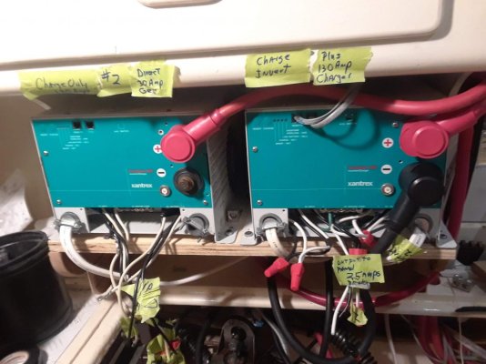
The two inverters can be piggybacked, better than 2 individual and saves separate wiring and extra panels.
The inverter(s) should be after the shore power or gen set selected, not one of the selections of the rotary switch, they have built in transfer function to begin sending power if none is passing through.
The two input, two output? your selector suggests you have shore/gen 220 volt shore power and likely genset, but the 2500 I find is 110 volt. Feedback frying inverter with 220? during selector switching. IMHO
 
Wiring Solved!!!

Thanks for the suggestions, I have looked at a lot of net stuff, also u tube, ie PYS videos. I am always trying to improve safety. My “expert” never would show, so I keep researching and came up with a plan. First I trace out all connections on the relay system. Really was surprised what I found. Two breakers were cut from the brass bar that was power supply and used as an switch for power coming from elsewhere! I removed the relay because I was told it might be causing feedback to inverter. Solution; I used the lead off my rotary switch for incoming Gen. I ran that to 2nd rotary switch and then back to original connection. At this point nothing changed. Then I ran inverter Output (10 ga) to the 3rd position on switch. The switch has 1, off, 2. I can label I 1 as Gen and 2 as Inverter. Everything works Now All the 120 outlets work on both panels. Just have to turn off big loads, only want outlets on when cruising. I was so stumped on how to connect to the existing rotary switch. Though about using shore 1 as the inverter part But way to hard to wire. Days of thinking ,hours to fix. I didn't take pics when finished, at home drs appt has delayed my response. I will post progression pic now .
IP Inverter.jpg
New 30 amp.jpg
 
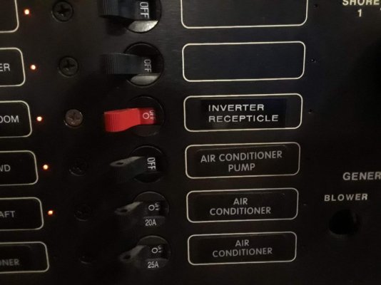
Inverter recepticle will be relabeled Inverter Power
 
Back
Top Bottom