CruisAir unit dead

The friendliest place on the web for anyone who enjoys boating.
If you have answers, please help by responding to the unanswered posts.

Rufus

Guru
Joined
Aug 16, 2017
Messages
906
Location
USA
Vessel Make
OA 440
Smelled burning wire insulation then the breaker popped. 16 ton stowaway unit.

Inspection of control/ logic board showed black and purple wires on the TRIAC switch fried and oil leaking from the start/run capacitor. Fabricated new TRIAC wires and reconnected the circuit board. The control panel and fan work fine. Compressor and cooling pumps won’ start, although there is a “click” near the compressor when the cool button is selected. A second click occurs a second later.

Meter checks this morning show power to the black and yellow TRIAC wires at all times (cool button on or off). Nothing on the purple TRIAC wire. No evidence of power transfer to the cooling pump wires. (The shared pump works fine on the second AC unit.

I’m planning to purchase another TRIAC switch, a start/run capacitor and a PTCR. Any other suggestions? Can I bypass the logic board and jump start the compressor to eliminate it as a failure? Other than these things am I facing the dreaded logic/control board replacement? Is there a place that refurbishes them? I’m not capable of trouble shooting a circuit board.

All ideas much appreciated. Thanks
 
Last edited:
There’s not an Hvac tech available for weeks in this area and I searched the internet for hours.

I want to bypass the logic/power circuit board to attempt a direct start of the compressor in order to establish whether it’s locked up. It appears that the thermal overheat switch and the high pressure switch are the only “protection” switches that could be malfunctioning in that circuit (other than the board itsel). If I jumper/bypass those two items (in the event they are stuck), and have a new capacitor installed, which wire on the compressor motor do I hook to the line power to see if it will spin?

The compressor has a black wire (via purple on the TRIAC switch) to the compressor C terminal, a pink wire from one side of the capacitor to the compressor “S terminal, and a white/red from the other capacitor terminal to the compressor “R” terminal. Would I also need to jumper the capacitor (in the event that something in the logic board is interfering?

If the compressor is dead, I’ll just purchase another unit. If it’s functional, I’ll send the board to Flight Sytems.
Thanks
 
Last edited:
Sounds like you are beating a dead horse. How old is the unit?

pete
 
The compressor being locked up wouldn't damage the board. So, I don't think there is much more of a risk of that now than there was an hour before the board failed.
 
The AC was installed in 2005, but has only been used intermittently during Great Lakes summers. That might add up to a year or two in Florida terms. So I don’t believe I’m beating a dead horse....just looking for someone who knows HVAC...
 
This is really hard to debug with no service documentation and without the model number to try to find any.

There is often a schematic on the unit, on the control box, or inside the cover of the control box. If you can find that, scan it or get a good photo of it, and post it, I can probably be of more help. Alternately, if you can post the exact model I can look and see if any info is already posted to the web.

Beyond that, you might want to take a look at a tutorial like this to see how to test the compressor, if you are comfortable and feel safe doing that, following the proper precautions, etc:
-- https://www.lennoxpros.com/news/the-proper-way-to-ohm-a-single-phase-compressor
 
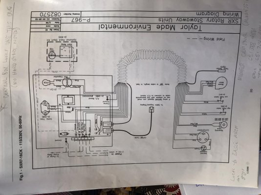
Thanks for responding. I’m messaging from my wife’s phone and I don’t know if or how to link. But the wiring diagram is on page 20 of the on-line publication called “SMX II control systems (DX)”. The compressor is Cruisair model SXF 16/1-RMT. It is a “stowaway” unit (and the wiring at the top of the compressor is almost touching the top of the seat bench structure...inaccessible without partially moving the unit). The logic panel/box is remote and easy to reach.

The diagram glued to the inside of the remote power/logic box is M1010097G and is titled SXF5-16(C/CK) Stowaway compact with SMX control. It is the same as the drawing in the on-line manual referenced above with one exception...there is no optional hard start circuit depicted (and not installed on my unit).

I’m going to read the item you attached next. I’m not versed in AC,but have been reading a lot. One thing I’d like to nail down is that the wire colors on the power cables are the same convention for marine and household.

Best I can figure, to completely bypass the circuit board for a quick jump start of the compressor, I’d hook the feed for the C terminal directly to the black wire in the power cable, and the capacitor feed would be connected to the white wire in the power cable (with the rest of the capacitor wires to the compressor attached per the drawing in the diagram). Then turn on the breaker at the wall switch. If no start it could be a faulty thermal switch or a faulty high pressure switch/ circuit. In that case I don’t could try to bypass/jump those switches. If still no start the compressor is likely finished. (This unit does not have a low pressure switch). Am I on the right track?
 
Last edited:
After reading the excellent tutorial, I disassembled the air delivery end of the unit so I could slide the whole assembly far enough to the left to access the compressor wiring and safety switches. Then I took ohm readings. The meter tended to “hunt” around but these are ballpark values when it settled down: C-R 0.9; S-C 4.3 ; S-R 5.1. I took multiple readings and CR plus SC never added exactly to SR, but they were in the ball park. I also checked the thermal overload and the HP switches and they each showed 0.3 on the ohm setting. So I believe that’s all good news??

Waiting on the new capacitor, TRIAC and PTCR to arrive. Still wondering if a direct start (bypassing the logic board) would yield useful info...
 
Last edited:
Yep. Good news. That all tests goods. It is overwhelmingly likely your problem is on the board.

I was away from the Internet yesterday, but will have some time this afternoon and will see if I can find and look at the schematic.

But, U really see no reason to suspect the comoressor.
 
I just went to look at that manual. But, I couldn't find what looked to be an applicable schematic. Can you paste the URL? You don't have to do anything fancy. Just cut and paste it into the message. If you want to post a photo of the schematic, hit the "Go Advanced" button then look for the paper clip, then "Choose File", then "Upload".
 
This address should get it:

www.tropicalmarineairconditioning.com/sheets/L-2362.pdf

It also pops up using .../L-064.pdf in the same address

As Imentioned in earlier post, the correct chart is on page 20 (but without the hard start or low pressure switch).

Thank you again for the help. The new capacitor, PTRC and TRIAC should be at the post office tomorrow.
 
Last edited:
Try this...Google “Cruisair P-967”. One of the pop ups is Dometic Southern Marine Supply Inc with a PDF document. The correct schematic is on page 21 of that 1100 plus page service document
 
Last edited:
I took a photo on this I-phone...now let’s see if I can attach it...

7608336A-1598-41C7-A34C-4372ED7A9650.jpg
 
Leaking Capacitor = Bad Capacitor

The fact that the op mentioned that the capacitor is leaking fluid indicates that it is bad. The compressor will not start with a bad start capacitor. The op's describes the unit clicking on start up and then clicking agin several seconds later. This is exactly what would happen with a bad start capacitor. Unit would try to start then go out on overload.

You can test a capacitor easily with an ohm meter. The capacitor should initially look like a dead short on the ohm meter. As the capacitor charges from the battery in the ohm meter the resistance will go up steadily to infinity (be sure to discharge capacitor by shorting it after making any tests).

Any other issues he may have are secondary.
 
As I said, I’m waiting on the mail for the capacitor and a new TRIAC switch. The interesting thing that happened during the failure is that two wires between the Triac switch and the board got so hot that the insulation burned off (and one of them...the power wire to the compressor....actually burned through the wire at the board terminal). I’d still like to bypass the board and jump start the compressor when I do get the new parts...then try a start with the board in the loop.
 
It sounds like protection components failed. Is there a way to test thermal overheat switch? Here's a youtube that may help.
With a bad cap, the compressor would try to pull maximum current causing thermal overheat. I give you credit for DIY as no tech available for weeks. I'm surprised that the circuit breaker didn't trip before the wire insulation melted. Major fire hazard. Usually breakers become weak and trip early. Very lucky there wasn't a fire.
 
So, that is more of a wiring diagram than a schematic. But, based on what is there and some guessing, my guess is that your real problem is the one associated with the triac, not with the capacitor.

The capacitor seems to be a run capacitor that is shunted by the PTCR during start-up. In other words, the capacitor is used to phase shift the power to make the compressor run well -- but not to get it started. It appears that, the capacitor is effectively removed from the circuit by the PTCR during start up so that it doesn't limit initial current.

Based upon your report that the capacitor is leaking, it should be replaced. Caps can fail open or closed or add series resistence. So, they can do bad things. But, it is unlikely that this one is what is preventing start-up. Even if it were open or had developed resitance, the motor would likely still start, just not run well. And, if it shorted, that would likely be more dramatic. So, please do replace it. And, doing so might make things run better -- but I don't think it is the reason things won't start.

If you want, check to make sure the PTCR is very low resistance after the unit has been off for a while. This would show that it is, at least initially, shunting the capacitor and allowing full current to the compressor.

I can't quite sort out the circuit from the wiring diagram alone. It doesn't show all of the connections the same way a schematic would. And, I can't trace it from here. But, from the looks of it (and, again, I make no promises), the yellow wire on the triac looks to be switching the connection between the purple and pink wires on the triac on and off. The distal end of the wire is labeled GT (Gate) and the position of the terminal shown on the triac is a common one for the gate. Having said that I still don't recommend bypassing anything (.)

You already checked your compressor and found no shorts. If you really, really want, you can investigate the pump. How does the wiring going to and from it look? Does it have a fuse? Is it blown? Is it the right size?

If you want, and know how to do it safely, you can disconnect the pump at the terminals and check it -- via a switched circuit and a the right size over-current protection device. If it blows the fuse or breaker, it could be what ate the triac.

You might also recheck the wires connectred to the ones you replaced via that terminal block and otherwise and make sure none show any heat damage and if so, check what is attached to the other side of them.

I can't emphasize strongly enough that you are dealing with a 120VAC circuit with the ability to supply enough current to hurt you, start a fire, etc. Sometimes it is worth a service call, even once you have the parts. A lot of times, for jobs I don't want to do, I pre-order parts and have them on hand for professionals. It is the best of both worlds -- money saves by having the parts on hand and saving trips, money saved on mark-up, time saved by having things fixed faster -- and the honed judgement and skill of a professional.
 
The pump works fine with the other AC unit. It won’t switch on for this dead one.

I too suspect the TRIAC switch, particularly because that is precisely where the burn marks are on the circuit box cover. I installed a spare when I fixed the burned wires. The wall control unit came back alive and the fan returned to operational. No pump and no compressor. But I’m not positive that spare TRIAC is ok, that’s why I ordered two more. Regardless, I suspect some small component failed on circuit board when it got so hot.

Yes it’s difficult to make sense of things without knowing what’s happening with the chip. New parts tomorrow. (By the way, the 15A for this unit
Did trip when I smelled smoke, and the 50A breaker for the boat cord connection had opened the day before.
I’m suspicious of a wonky cord adapter that allowed me to use a 30a dock supply in conjunction with the 50a socket on the side of the boat. It might have been internally arcing and screwing up the voltage to the TRIAC. That said, I got out the 50a cord when I noticed that connection was very warm. Maybe the damage was already done when the meltdown occurred the next day.

Thanks for your thoughts.
 
Last edited:
Hi Rufus,

The triac is what is switching the pump and compressor. The yellow wire is what should be causing the black hot wire to energize the purple wire.

If this isn't happening, either the triac is bad, or the current-limiting resistor has almost but not completely opened, or there is a problem with the return path for the triac, i.e. the circuit is not eventially completing back to neutral. What voltage are you measuring at the yellow wire when the system should be calling for the compressor and pump?

With everthing off and de-energized, is the purple wire leaving the triac electrically directly connected to the purple wire on the thermal overload by the compressor (I realize they may pass through the board, but is resistance near-0 ohms?)

What about the wite-reds to neutral?
 
Thanks for the continuing help. I’ll get those values tomorrow as my spouse is “currently” watching a PBS mystery from the seat over the access panel for the control/logic board. Priorities...
 
Follow up. I installed the new parts, which arrived today. No improvement. So I hot wired the compressor to the main power feed and flipped on the unit’s breaker. It started right up. With that knowledge I contactedFlight Systems. They promised a 48 hour turn around and said they have a 90 percent success rate on these boards. It goes in the mail in the morning. Thanks all. I learned a lot.
 
Last edited:
Very encouraging. Hope you have ample fans to keep you cool in the meantime.
 
So, my forward unit, a Webasco FCF 9000, went on a sympathy strike today.

The saga began a few days ago when the diver cleaned the bottom. As isn't uncommon if the unit is running while he is cleaning, the strainer became clogged and flow was noted to be reduced. I cleaned it and all was good.

A couple days later the condensation pan was noted to be draining to the bilge vs being sucked out by the Mermaid condensator venturi valve. The drip pan's tiny strainer, part of the Mermaid system, had become clogged with slime. I cleaned it and all was again good.

Last night flow was again noted to be reduced at the thru-hull discharge, but still plenty (I have a 500gph pump on a 9000btu unit...). Cleaning the main strainer was again put on "the list".

This morning I turned the unit off for a few minutes while running the hot water heater. Several seconds after I turned it on the Blue Seas 30A ELCI tripped, but the unit's 15A breaker did not. Not uncommon, the ELCI main blows faster than the conventional breakers upon high current. Wash. Rinse. Repeat.

Wanting just a hair more time to debug, I switched over to the genset, which bypasses the ELCI in favor of a conventional main. I got outside in time to see a trickle of a flow before it stopped -- the unit's /internal/ 5A time-delay fuse popped. Replaced it. Wash. Rinse. Repeat. Except the fuse blew almost instantly.

Disassembled, inspected, and cleaned pump. All looked good. Recleaned strainers. They weren't too bad.

Tried again, still on the generator, pop goes the fuse.

Wiring diagram. No schematic. Call Webasco tech support. No schematic available. "No user servicable parts inside. If board is bad, replace whole. Call dealer for pricing. Expect $100 or so."

Unscrewed neutral wire of pump from board. Fuse didn't pop. Quickly shut down unit as it had no cooling without pump.

Disassemble hose at mermaid condensator. Found it clogged with a barnacle. Must have earlier knocked it loose cleaning strainer. Cleaned and reassembled.

One more try, with pump reconnected and fuse replaced. Fuse popped.

Replaced pump.

All good. Proper flow. Fuse doesn't pop. No breakers pop, even on shore power.

Will see what SeaFlo says about warranty. 11 month old pump. 4 year warranty.

My pump was preventing my compressor from starting by popping the breaker. And, only once a slower breaker was in use did the fuse pop. So, yes, a 30A ELCI popped faster than a 5A time-delay fuse.

If you've got a shared pump and it is otherwise working, check the relay. With checking before sending out board. Fast and easy to do. (Of course, not saying it isnt bosrd, just offering feasible things to check before spending money...)
 
Last edited:
Per your suggestion I checked that the pump runs from the power wires on the circuit board....checked out OK. Actually, the pump relay function is part of the board circuitry on the Cruisair system. Subsequently mailed the board to Flight Systems. Currently praying fo a week of cool weather.. . 70’s would be ideal.

Thanks again for the advice.

PS. Last summer the venturi suction device on our unit clogged and flooded the salon floor overnight...tiny mesh screen inside the vacuum canister...don’t know if it’s a mermaid, but same principal of operation.
 
Thanks for responding. I’m messaging from my wife’s phone and I don’t know if or how to link. But the wiring diagram is on page 20 of the on-line publication called “SMX II control systems (DX)”. The compressor is Cruisair model SXF 16/1-RMT. It is a “stowaway” unit (and the wiring at the top of the compressor is almost touching the top of the seat bench structure...inaccessible without partially moving the unit). The logic panel/box is remote and easy to reach.

The diagram glued to the inside of the remote power/logic box is M1010097G and is titled SXF5-16(C/CK) Stowaway compact with SMX control. It is the same as the drawing in the on-line manual referenced above with one exception...there is no optional hard start circuit depicted (and not installed on my unit).

I’m going to read the item you attached next. I’m not versed in AC,but have been reading a lot. One thing I’d like to nail down is that the wire colors on the power cables are the same convention for marine and household.

Best I can figure, to completely bypass the circuit board for a quick jump start of the compressor, I’d hook the feed for the C terminal directly to the black wire in the power cable, and the capacitor feed would be connected to the white wire in the power cable (with the rest of the capacitor wires to the compressor attached per the drawing in the diagram). Then turn on the breaker at the wall switch. If no start it could be a faulty thermal switch or a faulty high pressure switch/ circuit. In that case I don’t could try to bypass/jump those switches. If still no start the compressor is likely finished. (This unit does not have a low pressure switch). Am I on the right track?


Not sure if you have resolved your issue..but I may have all the electrical components for this system. I had a 16k stowaway set up where the compressor went out. I have all the controls and control board if you interested.
 

Latest posts

Back
Top Bottom