paravane stabilizer: solid foldaway arms design

The friendliest place on the web for anyone who enjoys boating.
If you have answers, please help by responding to the unanswered posts.

balder8

Senior Member
Joined
Aug 15, 2018
Messages
103
Location
France
Vessel Name
BALDER VIII
Vessel Make
North Sea Trawler 57' OC
Hi!
Bonjour à tous,

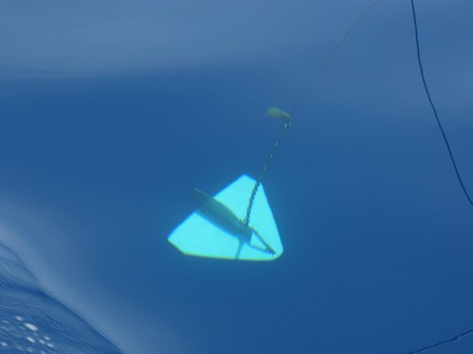
First of all, thanks to all boaters and trawler owners who are posting pics, drawings, comments and explanations concerning this very crucial subject on passagemaker trawlers: the paravane design as unique system for stbailization underway or as a back up for long range cruising.

I think trawlerforum is certainly the only one forum where you can find this level of quality! With a very friendly atmosphere!

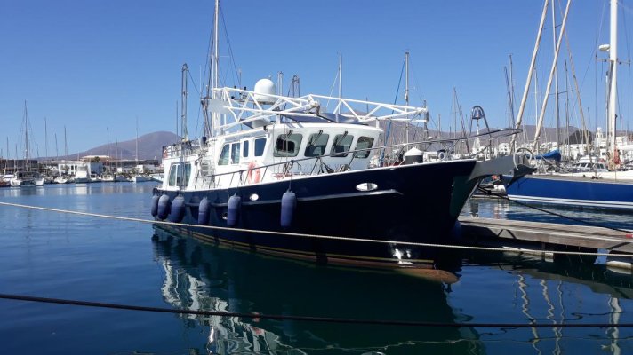
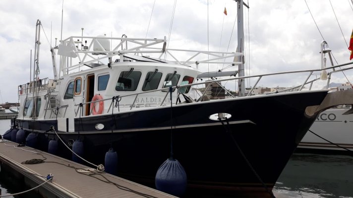
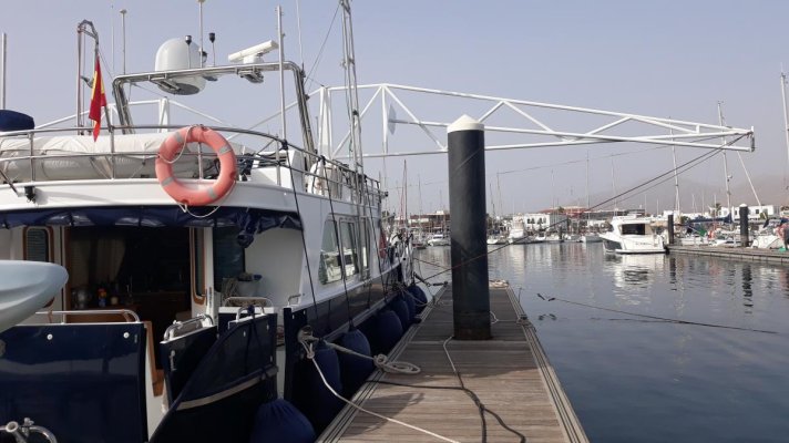
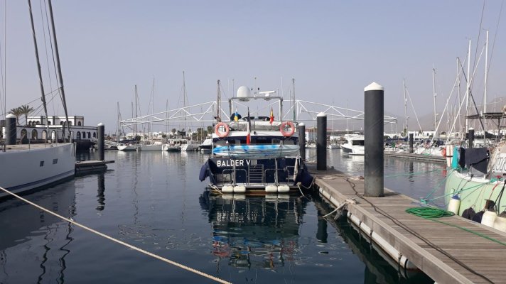
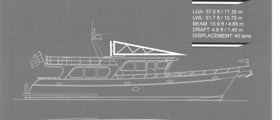
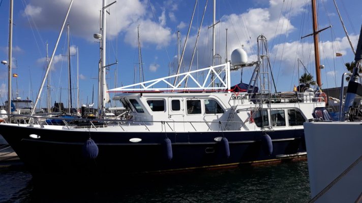
So, I have decided to go with paravanes as a back up ( I have Keypower stabs installed) for my next ocean crossing aboard Balder VIII, north sea trawler 57' built by excellent Dutch boat yard Tinnemans'BV.

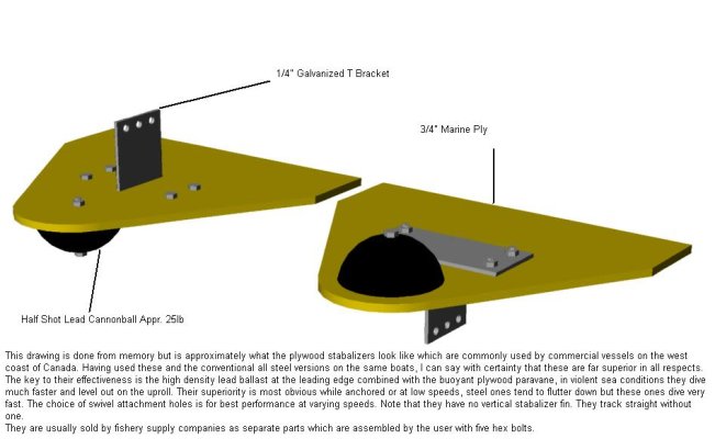
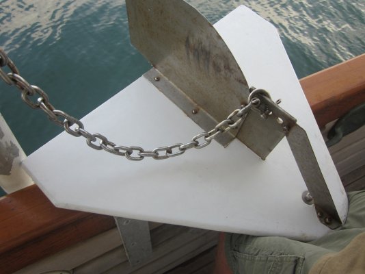
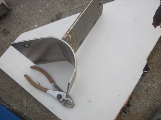
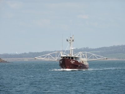
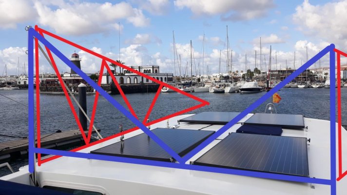
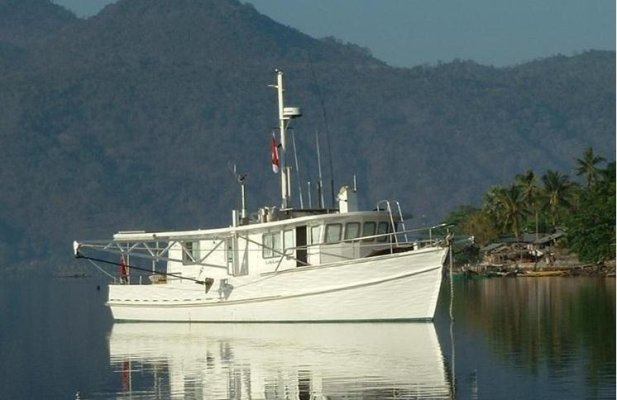
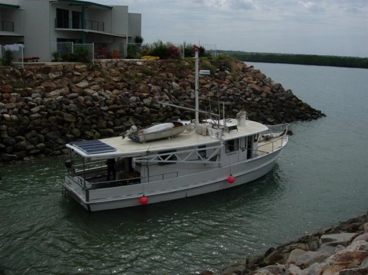
Instead of considering an extra A frame design with mast etc, as used on Nordhavn, KageyKrogen and described in the fantastic book " Voyaging under power", I am planning to retrofit a stainless steel rigid structure based on an horizontal solid foldaway arms/stabilizer design as shown below on the picture of the australian fishing boat shown on M/V Dirona blog ( thanks to them!)

On my plan, paravanes are 20' long. An engineer is calculating the diameter and sizes of all this rig, may be in stain less steel.
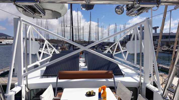
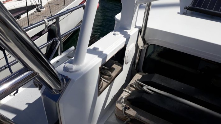
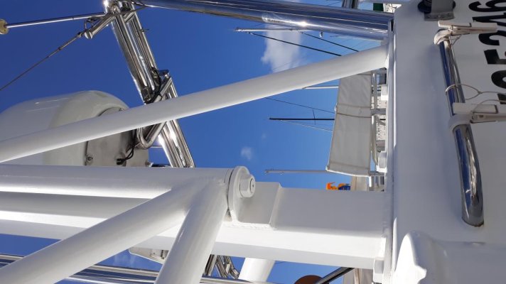
Here some pictures of my project.

Is it necessar to say that all comments or advices will be welcome and appreciated???

Kind regards
Dominique
 

Attachments

  • Projet Paravane horizontal et bidirectional DEC 3.jpg
    Projet Paravane horizontal et bidirectional DEC 3.jpg
    72.8 KB · Views: 110
  • Schema paravane horizontaux balder 8.pdf
    371.2 KB · Views: 39
  • Project PARAVANE vue de dessus avec renfort transversal.jpg
    Project PARAVANE vue de dessus avec renfort transversal.jpg
    121.3 KB · Views: 112
  • paravane horizontale.jpg
    paravane horizontale.jpg
    91.2 KB · Views: 145
  • projet PARAVANE horizontal et bidirectional DEC .jpg
    projet PARAVANE horizontal et bidirectional DEC .jpg
    121.2 KB · Views: 113
You are going to be pushing our collective memory of statics class!
There is a likely heavy load, alternating, on the base supports. That fixed bottom blue tube will load the bottom vertical supports quite significantly, I believe, with both a bending moment and a shear force. So, those are significant anchor requirements. Is the superstructure Al or steel?

Beyond that, consider the arms of titanium, or is money limited?:flowers:
 
Yes, diver dave is correct as above. The bending moment will be taken care of by the horizontal truss structure. But the vertical and sheer force on that blue member will be quite significant.

So make sure someone looks at the underlying structure below those blue members as well as the design of the arms and truss.

David
 
Thank you Diver Dave, thank you DJ Marchand!

Yes I know there will be a serious load on the underlaying structure!

Hull and superstructure of Balder VIII are built from marine steel 6 to 8 mm.

I wish the calculation should be accurate to avoid transform my beloved trawler in a convertible one in rough seas!

Seriously, I want to avoid the vertical pole, chain or cable as well, adding weigth in the heights.

The picture below from a Trawlerforum member is also typical of this design.
About Titanium, I am paying too much taxes in France to afford this kind of material, as well gooooold!
 

Attachments

  • 1_Lifeline50cropped.jpg
    1_Lifeline50cropped.jpg
    64.8 KB · Views: 106
  • 1_Lifeline925.jpg
    1_Lifeline925.jpg
    113.3 KB · Views: 115
Also, in the retracted position: Be sure to support the movable arm from below, well aft. Otherwise there is a significant bending moment to aft on the lone vertical support pole that has no strut bracing in this direction. This is obviously the same port and starboard. Even with this, a high seas transition from retracted to extended will stress these masts. You might think about a strut guy or even conventional wire rope guys up high.
Note that your two example pictures show pole attachment high and low.
 
Last edited:
Also, in the retracted position: Be sure to support the movable arm from below, well aft. Otherwise there is a significant bending moment to aft on the lone vertical support pole that has no strut bracing in this direction. This is obviously the same port and starboard. Even with this, a high seas transition from retracted to extended will stress these masts. You might think about a strut guy or even conventional wire rope guys up high.
Note that your two example pictures show pole attachment high and low.

Yes it is exact. I am waiting for the calculation of the Bureau d'Etude.
 
I have added the red triangle, forgotten.
 

Attachments

  • projet PARAVANE horizontal et bidirectional DEC .jpg
    projet PARAVANE horizontal et bidirectional DEC .jpg
    121.3 KB · Views: 86
I have added the red triangle, forgotten.

:)

Intending any mainsail from the foremast? I suppose only a closehauled situation? Or, will paravanes eliminate future use of sail?

Oh sorry; was confused by vessel behind.
 
.

The picture below from a Trawlerforum member is also typical of this design.
About Titanium, I am paying too much taxes in France to afford this kind of material, as well gooooold!

M.V.Lifeline
Tragic story there and vessel is still up in Kota Kinabalu I think.

You will notice their top beam/truss arrangement has a horizontal top and bottom whereas you only have a bottom drawn.
On yours I believe you will get upwards bending from the centre unless you ad a top beam.
 
Well said above.

Fascinating approach. As mentioned above, bending moment and shear forces abound. If it were my boat, I’d see the solution as two separate problems. One, I’d want to consider what it would take to transfer the forces from the bird through the boom and to the points of attachment as a force requiring a material and structure of one yield strength, and the forces placed on the center mast section attached to the boat as forces requiring a separate and much higher yield strength material, integrated with the boat’s structure.

The boom design as shown looks adequate for this sort of stress constructed from simple schedule 40 tubular aluminum. But to transfer that much leverage through that center section design as an add-on, non-integrated accessory with no compression mast or direct connection across the farthest points of leverage....shew! I’d sure need to have a lot of faith in my boat. Interesting challenge.

I know you’re just opening to feedback here, but at the very least, I’d want a glaring green light from a darned good naval architect. Please keep us updated!
 
Last edited:
M.V.Lifeline
Tragic story there and vessel is still up in Kota Kinabalu I think.

You will notice their top beam/truss arrangement has a horizontal top and bottom whereas you only have a bottom drawn.
On yours I believe you will get upwards bending from the centre unless you ad a top beam.

"Tragic story there"... I do not want to be impolite, I believe you know something very sad about this vessel or the owners or family...

"On yours I believe you will get upwards bending from the centre unless you ad a top beam". Thanks a lot for this comment, I will try to translate it and transmit to the technician.
To Healhustler,
Well said again.. the problem for me as an european boat owner, quite experienced as well, is that we know nothing about paravanes, rig and all the stuff. Because, here, fishing boats are not using these kind of stabies.And by the way, trawlers owners do not share or reply their experiences.
When I compare the US culture and the Australian or NZ practices , the big difference is the way you are rigging the arms: vertically in US and more horizontally in Pacific. Horizontally folding with rigid arms looks more easy to deploy and retrieve, isn'it?
Of course, lack of A Frame or mast means more solid structure to support the load.
 
Well said above.

Fascinating approach. As mentioned above, bending moment and shear forces abound. If it were my boat, I’d see the solution as two separate problems. One, I’d want to consider what it would take to transfer the forces from the bird through the boom and to the points of attachment as a force requiring a material and structure of one yield strength, and the forces placed on the center mast section attached to the boat as forces requiring a separate and much higher yield strength material, integrated with the boat’s structure.

The boom design as shown looks adequate for this sort of stress constructed from simple schedule 40 tubular aluminum. But to transfer that much leverage through that center section design as an add-on, non-integrated accessory with no compression mast or direct connection across the farthest points of leverage....shew! I’d sure need to have a lot of faith in my boat. Interesting challenge.

I know you’re just opening to feedback here, but at the very least, I’d want a glaring green light from a darned good naval architect. Please keep us updated!

Well, after two months, back aboard to finish my paravane project!
Here is the result, but the birds are not done. Plywood or steel, I try to find the best solution and drawing: 300 sq inches or more?. Before COVID 19 flu, I expected to order from Kolstrand but shipping cost was too expansive. Will weld or build locally.
Also , very difficult to imagine which angle for the swivel attachment hole???
Any suggestion appreciated!
 

Attachments

  • 20200527_162446.jpg
    20200527_162446.jpg
    112.3 KB · Views: 99
  • 20200531_163328.jpg
    20200531_163328.jpg
    96.6 KB · Views: 108
  • WoodFish.jpg
    WoodFish.jpg
    73 KB · Views: 458
I'd go with the 3/4" plywood that you have in the drawing. If they come in contact while deploying or retrieving, the wood won't scratch the side of your boat. Ours uses stainless steal with 27.5 lb lead weight up front. For scaling purposes, ours measure ~28" across the back and we displace 44,000 lbs. I'd consider going up to 32" size based on the size of your boat.

Here's a picture of how ours are attached, while underway and who we bought them from.

https://www.englundmarine.com/products/stano-stabilizers--fish-|SNO-STAB.html

Nice job by the way!
 

Attachments

  • 1b.jpg
    1b.jpg
    187.6 KB · Views: 412
  • 069.jpg
    069.jpg
    33.3 KB · Views: 70
I'd go with the 3/4" plywood that you have in the drawing. If they come in contact while deploying or retrieving, the wood won't scratch the side of your boat. Ours uses stainless steal with 27.5 lb lead weight up front. For scaling purposes, ours measure ~28" across the back and we displace 44,000 lbs. I'd consider going up to 32" size based on the size of your boat.

Here's a picture of how ours are attached, while underway and who we bought them from.

https://www.englundmarine.com/products/stano-stabilizers--fish-|SNO-STAB.html

Nice job by the way!

Bonjour Larry M,
Thank you very much for your kind comment!
I have spent a lot of time reading your posts and looking at your pictures before starting my project! As mentionned, here, in Europe, even naval architects know nothing about paravanes...and most of people consider it is uggly... I assume my choice and if I cross Atlantic next winter ( depending of bloody flu, situation in US, taxation here to support economy, to resume all good news to come may be in the next six months, etc...)I will be happy to have a back up to my hydraulic stabilizers.
One more question, going to with plywood 32" local made (Englund does n't ship oversea and I have no chance, sadly, to visit my house in Québec...), is the vertical stabilizer really usefull or may I follow the drawing in my post?
Last but not least, on my boat, we have fitted a rigid pipe with a welded plate like they do in NZ but I think it is too heavy. So these plywood paravane with high density lead ballast look more easy to use.
Last , would you only recommand dyneema rope to connect from the paravane to the bird instead of chain??
 
Well said above.

Fascinating approach. As mentioned above, bending moment and shear forces abound. If it were my boat, I’d see the solution as two separate problems. One, I’d want to consider what it would take to transfer the forces from the bird through the boom and to the points of attachment as a force requiring a material and structure of one yield strength, and the forces placed on the center mast section attached to the boat as forces requiring a separate and much higher yield strength material, integrated with the boat’s structure.

The boom design as shown looks adequate for this sort of stress constructed from simple schedule 40 tubular aluminum. But to transfer that much leverage through that center section design as an add-on, non-integrated accessory with no compression mast or direct connection across the farthest points of leverage....shew! I’d sure need to have a lot of faith in my boat. Interesting challenge.

I know you’re just opening to feedback here, but at the very least, I’d want a glaring green light from a darned good naval architect. Please keep us updated!

Yes indeed,
Some details of the fitting ( not already tested to be honest)
The supports on starboard and portside are bolded with 4 cm diameter bolts. counterplate in 7mm hull more or less in the gravity center position.
The arms are articulated with a solid stainless tube 25mm inserted in two bronze rings. Material is galva steel.
Hope my google translation from french is ok!!!
 

Attachments

  • 20200603_110237.jpg
    20200603_110237.jpg
    153.4 KB · Views: 70
  • 20200603_110300.jpg
    20200603_110300.jpg
    103.3 KB · Views: 67
  • 20200603_110332.jpg
    20200603_110332.jpg
    80.4 KB · Views: 66
... is the vertical stabilizer really useful or may I follow the drawing in my post?

I’ve never run with out the vertical stabilizer. I have tuned them though. Based on current and wave height, I’ve bent the stabilizer slightly to track parallel to the boat.

You could start without the stabilizers and easily add them later
.

Last but not least, on my boat, we have fitted a rigid pipe with a welded plate like they do in NZ but I think it is too heavy. So these plywood paravane with high density lead ballast look more easy to use.


I’ve used both. I like the plywood. As I mentioned, they are more user friendly when they come in contact with anything. I have seen where others have replaced the plywood with high density polyethylene/plastic for longevity. I was getting about five plus years before I had to replace the plywood.


Last , would you only recommend dyneema rope to connect from the paravane to the bird instead of chain??

I think it depends on your retrieval method. I bring the fish along the side of the boat and manually lift them. I’m not sure my hands could get a tight enough grip on the dyneema to lift the fish over the cap rail. The dyneema would definitely have less drag though.

Dominique: The picture is what happens after the plywood has been soaking for 5 plus years and fails when fully loaded. :facepalm:

Here's the contact information for the guy who makes the stabilizers for Englund Marine Supply. Maybe he can ship what you want with out the lead?

Harold Williams, F/V Snapper Products
360-580-0114

Larry
m/v Hobo
 

Attachments

  • 035a.jpg
    035a.jpg
    157.1 KB · Views: 64
I use Dyneema rope on my stabilizers and it has worked out great. Much better than the stainless cable they were rigged with when I got the boat. I pull them up by hand. I have a pair of heavy duty rubber gloves I put on before I pull them up. One thing that worries me about having the fish in the water is the possibility of accidentally snagging one on something while in shallow water and near rocks, (I have kissed the bottom before, but never got stuck.) I like the idea that Dyeneema could be cut easily in an emergency situation. Much easier than chain or cable.
 
Thank you again Larry, thank you Snapdragon for your replies!
 
Can you share your cost for this project? Thanks.
 
Hello,

Why you don't ,partially at less, use the existing structure ?

To low ?
 
Personally gone off the idea a bit.

Cruising the QLD coast at present and, as we have always done, waited for weather to suit our main course

Where we have actually wanted, not necessarily needed stabilisers has been when we hooked it around beam on for a spell as we entered an anchorage or, as we left an anchorage on the wrong angle before turning on an angle that worked.

In all of the instances, due to shallows, rocks etc, I feel the fish could not have been deployed safely.
As confirmation, those that had them and left, did not have them out due to the above and rolled abysmally.
We sat at anchor and felt pretty good about waiting. (-;
 
Last edited:
Can you share your cost for this project? Thanks.

Sorry for the delay to reply...

For the maths, size of pipes, load factors etc, I had no support from a naval architect. Engineers ask 2000 EUR including VAT for drawings, plans and calculation.
A local workshop in Arrecife did the work and sell the materials in galva steel with custom stainless tube and bronze rings for the pivoting arms. They transported all the structures and fitted it on board with counterplates, I did the paint job my self with bi component epoxy paint.
The cost was 8000 EUROS . I have to add some dyneema rope and accessories like electric LENCO actuators ( I am not sure to use it), consider 500 EUR more ( not including LENCO actuator
 
Interesting post balder8, I hope you have success with the end result, it’s sounds like you are getting set up for some serious cruising.

They say it’s a small world, especially within the boating community, but when reading your OP I noticed the pic you posted of the red/maroon coloured fishing boat, is a well known local (to me) boat. The horizontal paravanes are widely used in our states Wild West coast waters, and well proven over many decades of use.
 

Attachments

  • 963B4487-7819-492E-BC31-8C855EF256C2.jpeg
    963B4487-7819-492E-BC31-8C855EF256C2.jpeg
    77.9 KB · Views: 160
Thank you Southern Boater. Well said! I found the picture mentionned above in the excellent blog of M/V Dirona, a very experienced couple travelling seriously aboard their Nordhavn.
I recommand their blog very well documented.
Without COVID 19, I would have considered a journey ( by plane...) to do some reseach in your georgeous country to understand, in real conditions, how you tune and fit your paravanes.
From what I see, there is no hinge connecting the triangular plate to the rigid tube. So, may I ask you how you determine the angle when welding this plate, and the surface of it?
I have not already test my system . It looks heavy, and I have planned, next september to test also the paravane rig with the ''classic'' bird like explained by Larry M but of course, using the horizontal structure now fitted.
 
Last edited:
I will see what I can find out by asking the local fishermen and let you know.
This is a great and welcoming country to holiday in, but being geographically so far from Europe/US, we don’t see too many visitors from your areas.
 
Thank you so much Southern Boater! If you can take some pictures of these paravanes, I will be very happy to understand how fishermen are using these stabilizers.

Feel free as well to contact me by PM if you or friends or family need some infos concerning travelling, boating, business, politics or whatever you may need in Europe, specially France, UK and Spain!
 
It is interesting to see the tips below the level of the pilothouse roof...they are quite higher here on North America's west coast. Do the tips ever touch/drag in the water?
 
It is interesting to see the tips below the level of the pilothouse roof...they are quite higher here on North America's west coast. Do the tips ever touch/drag in the water?

Bonjour MurrayM,
If I understand your question, you are talking about the height between the base of the arm and the surface of the water when fully open at 90°? I am not currently aboard but I remember it was approximatively 12 feet.
I measured that considering the overall lenght of the two arms opened at 90°, if the boat is heeling at 15% on starboard or portside, the paravane should hit the surface of the sea.
If you are looking at the fishing boat from Tasmania above, it does n't look to be very high as well.
 

Attachments

  • 20200308_172928 (1).jpg
    20200308_172928 (1).jpg
    107.9 KB · Views: 34
  • 20200308_172950 (1).jpg
    20200308_172950 (1).jpg
    113 KB · Views: 38
..........Feel free as well to contact me by PM if you or friends or family need some infos concerning travelling, boating, business, politics or whatever you may need in Europe, specially France, UK and Spain!

....and likewise yourself b8, once the world starts moving again.
 
Back
Top Bottom