You are using an out of date browser. It may not display this or other websites correctly.
You should upgrade or use an alternative browser.
You should upgrade or use an alternative browser.
World's Largest Diesel Engine
- Thread starter charles
- Start date
The friendliest place on the web for anyone who enjoys boating.
If you have answers, please help by responding to the unanswered posts.
If you have answers, please help by responding to the unanswered posts.
Baggiolini
Senior Member
Can you imagine the gph? I think they go in excess of of 30kts
markpierce
Master and Commander
- Joined
- Sep 25, 2010
- Messages
- 12,557
- Location
- USA
- Vessel Name
- Carquinez Coot
- Vessel Make
- penultimate Seahorse Marine Coot hull #6
Can you imagine the gph? I think they go in excess of of 30kts
Human creativity continues to amaze.
FF
Guru
- Joined
- Oct 12, 2007
- Messages
- 22,552
"Can you imagine the gph? I think they go in excess of of 30kts"
Its the efficiency that counts , check the LWL and its not very fast at all SL 1 or so.and with 6000 to 7000 TEU ( Containers) per boat, goods still get wherever really cheaply.
FF
Its the efficiency that counts , check the LWL and its not very fast at all SL 1 or so.and with 6000 to 7000 TEU ( Containers) per boat, goods still get wherever really cheaply.
FF
OP
OP
charles
Senior Member
In the same vein:
Iron Giant - Magazine - The Atlantic
This, is a real forging press, you just thought that the diesel engine was a peice of work.
Iron Giant - Magazine - The Atlantic
This, is a real forging press, you just thought that the diesel engine was a peice of work.
RickB
Guru
- Joined
- Oct 20, 2007
- Messages
- 3,804
- Vessel Make
- CHB 48 Zodiac YL 4.2
Papa Charlie
Senior Member
Now that is a big engine. When I first got out of college I was a field service rep for Transamerica Delavel "Enterprise" Engine Div. Our engines were diesel, Bunker C and Digester (Methane from waste plants) gas fired. From 6 cylinder in line to 20 cylinder V config. They were 15 inch bore and 21 inch stroke and spun at 450 RPM. Considered the small block in the slow speed diesel industry. The 20 cylinder produced 12,000 bhp. There are two of the 16 cylinders in the US Steel 1200 foot Ore Carrier the Edwin H. Gott in the Great Lakes. They also made a 16 cylinder version that was direct reversible. Meaning it could run in reverse.
What is amazing about the diesel in this thread is that its torque is 5.6M ftlbs.
By the way, the fact that they call the engine a diesel is not directly related to the fuel but simply means that it is fired by compressing the gases and fuel to the point that it self ignites. The engines that I worked on started on diesel then were switch over to Bunker C fuel then switched back prior to shutting down to clean out the fuel lines and injectors. They were not allowed to run on Bunker in the harbors.
Bunker C has to be heated to 250 F for it to flow and be injected into the cylinders. If you spill any, just wait for it to cool and pick it up with a shovel.
One last bit of trivia: The 20 cylinder was about 35 feet long and three stories high. From cold to normal operating temperature the engine would grow almost 6 inches in length.
Probably more info than anyone was interested in but, there you go.
Last edited:
RickB
Guru
- Joined
- Oct 20, 2007
- Messages
- 3,804
- Vessel Make
- CHB 48 Zodiac YL 4.2
Man would I like to see the Plasigauge and torque wrench used on that assembly!!")
We use hydraulic "jacks" to stretch the bolts to a calculated dimension based on pressure applied. Will post pics later, am at conference trying to stay awake listening to guy talk about CBP and ANOA requirements for foreign yachts.
RickB
Guru
- Joined
- Oct 20, 2007
- Messages
- 3,804
- Vessel Make
- CHB 48 Zodiac YL 4.2
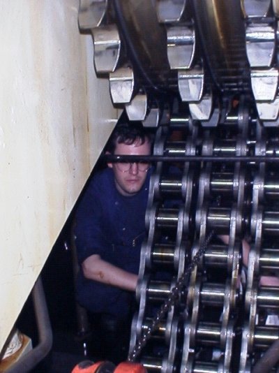
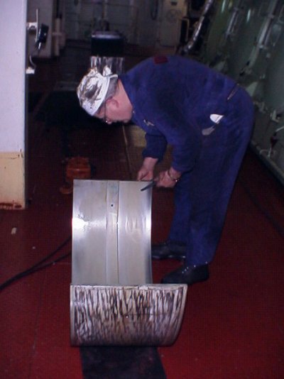
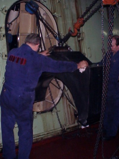
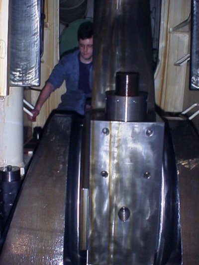
Here are a few pics showing a big end bolt and a "nut" and the jacks that stretch the bolts. If an assembly uses 4 bolts, like the main bearing cap shown being removed from the crankcase, we put a jack on each bolt and tighten all at the same time.
A cylinder head or cover uses 12 bolts and a "chandelier" from holds a jack for each one and all are tightened at the same time. The beauty of that system is that the nuts are literally just hand tight with a final snug with a small rod. You never break a sweat or a knuckle. The jacks are sized so that the same pressure is used no matter what size bolt.
A cylinder head or cover uses 12 bolts and a "chandelier" from holds a jack for each one and all are tightened at the same time. The beauty of that system is that the nuts are literally just hand tight with a final snug with a small rod. You never break a sweat or a knuckle. The jacks are sized so that the same pressure is used no matter what size bolt.
Attachments


Forkliftt
Guru
- Joined
- Oct 6, 2007
- Messages
- 2,450
- Location
- USA
- Vessel Name
- KnotDoneYet
- Vessel Make
- 1983 42' Present Sundeck
That's wild! Are the blue hydraulic lines attached to the "jack"? Are the fasteners threaded to be turned also? I sometimes have to "torque turn" headbolts. For instance 50 ft #'s and an additional 30 degrees. I bet these require some MAJOR torque!
RickB
Guru
- Joined
- Oct 20, 2007
- Messages
- 3,804
- Vessel Make
- CHB 48 Zodiac YL 4.2
Yes, the blue lines are the hydraulic supply to the jacks. If there are multiple bolts it is normal practice to tighten or loosen all of them at the same time to ensure equal forces on the parts being fastened.
Pages 7 and 8 of the document in this link show a cutaway of how a jack works:
http://mec.novomor.com/bw.files/BWServiceLetters/oil%20for%20hydraulic%20tools.pdf
There is no torque applied to the nut other than hand tightening to put the nut in its proper location.
When you torque a nut with a wrench you are actually stretching the bolt and that is what provides the holding force. The threads are an inclined ramp and when the nut is tightened it acts like a wedge to pull the bolt. The elasticity that makes the bolt want to return to its normal length provides the compression that holds the parts together. A jack stretches the bolt without all the friction of highly loaded threads and the surface of the nut on a washer or the part itself. You can apply tons of holding force without the drama and risks of long bars and torque multipliers or sledge hammers.
In case the drawing isn't all that clear, the jack screws onto the threads at the top of a bolt. A spacer between the jack and the part being bolted fits over the nut. If you look at the picture of the big end in a previous post you will see that the nut is smooth and round but has a couple of small diameter holes around it. The jack threads onto the exposed threads and the spacer fits over the nut but has a slot that will expose at least two of those holes. When the jack is pressurized to the correct level, the bolt will be stretched and a little "tommy bar" about 8 inches long by 1/4 diameter will fit in one of the holes and can loosen the nut.
The opposite procedure is used to tighten the bolt. The nut is spun on by hand and the jack installed over it. When the bolt is stretched the tommy bar is used to snug up the nut and after checking for complete contact under the nut with a feeler gauge, the job is done. We make a mark on the part and on the nut before loosening and confirm that those marks line up within a specified angle after retightening as a check that the bolt has not stretched beyond its ability to return to the correct length.
We use hydraulic wrenches on large steam flanges though. These actually rotate the nut a few degrees with each stroke of a hydraulic cylinder. They are fairly unsophisticated and only tighten on bolt at a time so the usual tightening pattern and judgement applies but they are more versatile than the dedicated jacks used on large diesels.
RickB
Guru
- Joined
- Oct 20, 2007
- Messages
- 3,804
- Vessel Make
- CHB 48 Zodiac YL 4.2
Now that is a big engine. When I first got out of college I was a field service rep for Transamerica Delavel "Enterprise" Engine Div.
My tug had a DMG-6 (direct reversing - 400HP @ 400 RPM) for power. I used to start it sometimes just to listen to it run.
Sigh ...
Forkliftt
Guru
- Joined
- Oct 6, 2007
- Messages
- 2,450
- Location
- USA
- Vessel Name
- KnotDoneYet
- Vessel Make
- 1983 42' Present Sundeck
I see what you are talking about from the picture. As the jack is screwed onto the "pulling threads", then pressure is applied and pushes against the bearing journal, the slots in the spacer allow you to hand tighten the nut. Once the "torque" is achieved and the position of the nut marked, pressure is reapplied. The nut is loosened, the pressure applied and the nut is agin spun into place by hand and the job is complete. Provided of course it doesn't spin any further than the first timeYes, the blue lines are the hydraulic supply to the jacks. If there are multiple bolts it is normal practice to tighten or loosen all of them at the same time to ensure equal forces on the parts being fastened.
Pages 7 and 8 of the document in this link show a cutaway of how a jack works:
http://mec.novomor.com/bw.files/BWServiceLetters/oil%20for%20hydraulic%20tools.pdf
There is no torque applied to the nut other than hand tightening to put the nut in its proper location.
When you torque a nut with a wrench you are actually stretching the bolt and that is what provides the holding force. The threads are an inclined ramp and when the nut is tightened it acts like a wedge to pull the bolt. The elasticity that makes the bolt want to return to its normal length provides the compression that holds the parts together. A jack stretches the bolt without all the friction of highly loaded threads and the surface of the nut on a washer or the part itself. You can apply tons of holding force without the drama and risks of long bars and torque multipliers or sledge hammers.
In case the drawing isn't all that clear, the jack screws onto the threads at the top of a bolt. A spacer between the jack and the part being bolted fits over the nut. If you look at the picture of the big end in a previous post you will see that the nut is smooth and round but has a couple of small diameter holes around it. The jack threads onto the exposed threads and the spacer fits over the nut but has a slot that will expose at least two of those holes. When the jack is pressurized to the correct level, the bolt will be stretched and a little "tommy bar" about 8 inches long by 1/4 diameter will fit in one of the holes and can loosen the nut.
The opposite procedure is used to tighten the bolt. The nut is spun on by hand and the jack installed over it. When the bolt is stretched the tommy bar is used to snug up the nut and after checking for complete contact under the nut with a feeler gauge, the job is done. We make a mark on the part and on the nut before loosening and confirm that those marks line up within a specified angle after retightening as a check that the bolt has not stretched beyond its ability to return to the correct length.
We use hydraulic wrenches on large steam flanges though. These actually rotate the nut a few degrees with each stroke of a hydraulic cylinder. They are fairly unsophisticated and only tighten on bolt at a time so the usual tightening pattern and judgement applies but they are more versatile than the dedicated jacks used on large diesels.
. What a creative and safe way to address this. How about the bearing inserts? Are the journals ever repaired/ reground on these bigger engines? Is the lube oil supplied through the crankshaft?
Last edited:
Papa Charlie
Senior Member
I enjoyed working on those big diesels. Very cool. I worked for 6 months on the assembly floor in the factory before heading out to work on them in the field. Great job straight out of college. I was traveling 9 months out of the year all over the world.
We use to use a 12:1 multiplier for torquing the head bolts. Total of eight 1.5" studs. Our mains were 13.5 inch.
I still remember the joke about the high speed diesel sales man. When they first introduced them they tried to sell them to the vessels working the river trade. The engineer on board asked if they could change a piston while the engine was running.
I worked on the old Fairbanks Morris OP engines they were cool. One of the strangest I have ever seen was a Wakishaw single cylinder engine, turned 60 rpm and had like a 3 foot diameter cylinder in it. Use for electrical generation. Was located in the power plant down in Homestead, FL. We had two of our 20 cylinders in that plant.
But that stuff you are working on is awesome.
meesterpearson
Newbie
Dmg-6
by chance, do you remember how many gallons per hour it burned?
My tug had a DMG-6 (direct reversing - 400HP @ 400 RPM) for power. I used to start it sometimes just to listen to it run.
Sigh ...
by chance, do you remember how many gallons per hour it burned?
- Joined
- Jun 25, 2008
- Messages
- 10,104
- Location
- Australia
- Vessel Name
- Now boatless - sold 6/2018
- Vessel Make
- Had a Clipper (CHB) 34
According to the article 1,660 GPH with %50 efficiency, automobile engines abt %35
by chance, do you remember how many gallons per hour it burned?
it's a very old thread, but the answer was here in post 8.
You're welcome...
meesterpearson
Newbie
it's a very old thread, but the answer was here in post 8.
You're welcome...
I was referring to the DMG-6 in your old tug. I am looking at an old tug with one. Thanks!
Warwgn
Veteran Member
5.6M ft Lbs, I would be scared if the prop got stuck the boat would start spinning!! That is very impressive, here is some more fun facts for gear heads!!
TOP FUEL DRAGSTER FAST FACTS:
ACCELERATION PUT INTO PERSPECTIVE
TOP FUEL DRAGSTER FAST FACTS:
ACCELERATION PUT INTO PERSPECTIVE
- One Top Fuel dragster 500 cubic inch Hemi engine makes more horsepower than the first 4 rows at the Daytona 500.
- Under full throttle, a dragster engine consumes 1-1/2 gallons of nitromethane per second; a fully loaded 747 consumes about the same amount of jet fuel with 25% less energy being produced.
- A stock Dodge Hemi V8 engine cannot produce enough power to merely drive the dragster's supercharger.
- With 3000 CFM of air being rammed in by the supercharger on overdrive, the fuel mixture is compressed into a near-solid form before ignition. Cylinders run on the verge of hydraulic lock at full throttle.
- At the stoichiometric 1.7:1 air/fuel mixture for nitromethane, the flame front temperature measures 7050 degrees F.
- Nitro methane burns yellow. The spectacular white flame seen above the stacks at night is raw burning hydrogen, dissociated from atmospheric water vapor by the searing exhaust gases.
- Dual magnetos supply 44 amps to each spark plug. This is the output of an arc welder in each cylinder.
- Spark plug electrodes are totally consumed during a pass. After halfway, the engine is dieseling from compression plus the glow of exhaust valves at 1400 degrees F. The engine can only be shut down by cutting the fuel flow.
- If spark momentarily fails early in the run, unburned nitro builds up in the affected cylinders and then explodes with sufficient force to blow cylinder heads off the block in pieces or split the block in half.
- Dragsters reach over 300 MPH before you have completed reading this sentence.
- In order to exceed 300 MPH in 4.5 seconds, dragsters must accelerate an average of over 4 G's. In order to reach 200 MPH well before half-track, the launch acceleration approaches 8 G's.
- Top Fuel engines turn approximately 540 revolutions from light to light!
- Including the burnout, the engine must only survive 900 revolutions under load.
- The redline is actually quite high at 9500 RPM.
- THE BOTTOM LINE: Assuming all the equipment is paid off, the crew worked for free, and for once, NOTHING BLOWS UP, each run costs an estimated $1,000 per second.
Warwgn
Veteran Member
14 cyl, 1660 GPH at 102 RPM
118.57 GPH per cyl
two stroke 102 RPM = 51 power strokes per min or 3060 PH
118.57 / 3060 = .0387 Gallons per stroke?
Math is not my strong point so all of that is suspect!!
So for all 14 cyl that would be .542 Gallons per stroke for the engine I think
118.57 GPH per cyl
two stroke 102 RPM = 51 power strokes per min or 3060 PH
118.57 / 3060 = .0387 Gallons per stroke?
Math is not my strong point so all of that is suspect!!
So for all 14 cyl that would be .542 Gallons per stroke for the engine I think
Last edited:
Warwgn
Veteran Member
Not sure, i know its 2 strokes per revolution, so i guess your right. So got to double my numbers then.
FF
Guru
- Joined
- Oct 12, 2007
- Messages
- 22,552
For folks with Detroit 2 strokes , the injectors come with a "CC" rating.
It is the amount of fuel pumped in 1,000 injections not just one.
It is the amount of fuel pumped in 1,000 injections not just one.
Ski in NC
Technical Guru
1660gph/14 cyl is 118gph per cyl
102rpm is 6120 hits per hour
118gph/6120hits per hour is 0.019gal/hit
128oz per gal x 0.019gal/hit is 2.48oz per hit.
An old crusty ships engr told me it was a shot glass per hit on his engine. Being old, it was a smaller but similar engine. So the numbers seem to jive.
102rpm is 6120 hits per hour
118gph/6120hits per hour is 0.019gal/hit
128oz per gal x 0.019gal/hit is 2.48oz per hit.
An old crusty ships engr told me it was a shot glass per hit on his engine. Being old, it was a smaller but similar engine. So the numbers seem to jive.
Last edited: