Does anyone know the mechanism of a Flexible drive coupler?

The friendliest place on the web for anyone who enjoys boating.
If you have answers, please help by responding to the unanswered posts.

kp cheung

Member
Joined
Nov 5, 2013
Messages
12
Location
Hong Kong
Vessel Name
19966
Vessel Make
Hiptimco 42
With the quarantine going on I've decided to focus my effort on the shaft area of both my engines (hence my first post a little while back). My current problem is that when there is a lot of resistance from the propellers, the drive coupler gives way and the gearbox spins itself but not the shaft. I assume this has something to do with the coupler as the gearbox is spinning (oil pressure is present, hence it has to be spinning). I am not too familiar with the mechanism of the coupler, if someone would be able to explain it to me that would be fantastic.

I've got some photos of the coupler below:
 

Attachments

  • WhatsApp Image 2020-05-03 at 9.22.23 AM (1).jpg
    WhatsApp Image 2020-05-03 at 9.22.23 AM (1).jpg
    91.7 KB · Views: 129
  • WhatsApp Image 2020-05-03 at 9.22.23 AM.jpg
    WhatsApp Image 2020-05-03 at 9.22.23 AM.jpg
    79.3 KB · Views: 143
Couplings can have different mechanisms. I don't recognize yours to know how they work. Sorry I can't be more help.

But, I do have a few of questions. What type of transmission is it? And, how do we know the transmission isn't slipping vs the coupling? How does it sound when functioning normally? While there is a lot of slippage?

Depending upon the transmission, the oil pressure may come from the engine side vs the shaft side.
 
Interesting looking coupling. Can you describe it a little? Is it two plates bolted together with something flexible sandwiched between the plates? A version of a 'flexible coupling?'

Greg.
 
In the first picture is that big hex nut for a compression fit to the shaft? Try to tighten the nut into the back hub and see if the prop and shaft turn then when the transmission output is turning. It will take a few hunded ft/lbs I would guess.
 
What you have certainly looks like a flexible shaft coupling. Greg described the basic typical construction of how most of them are made, the intent being to reduce structure borne noise from the shaftline.

What you describe is more like a clutch function, as in resistance at the prop disengages the shaft. Not knowing the construction of your unit, for the typical coupling this would not happen.

For a typical coupling its usually 2 things that happen:

Almost always a significant vibration occurs which causes the operator to reduce speed and seek repair. This is because the resilient medium(rubber?) is damaged, worn or compromised by something like a contaminant. Most couplings are designed to get you home, although sometimes at reduced speed.

The other type failure is the medium fails and the shaft doesn't spin at all.

In reading your description it seems you are basing some of your assumption on: "oil pressure is present, hence it has to be spinning" and not a MKI eyeball observation. Maybe take a look and see what's actually happening.

gkesden makes a good observation, it may not be the coupling at all. As I mentioned they do not "usually" act as clutches as you describe, but transmissions do.

Transaxial also notes something worth looking at, and if this is happening the shaft may be scored from the bolt slipping. Often hubs for shafts are keyed and the key may have broken as well, although this should fail and not act as a clutch.

:socool:

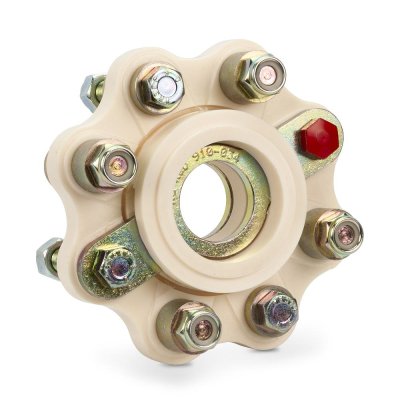
An R & D Flexible Shaft Coupling
 

Attachments

  • 910-034-001_e7ecb564-3f73-4ec1-bdce-e1d8e1fec9e8.jpg
    910-034-001_e7ecb564-3f73-4ec1-bdce-e1d8e1fec9e8.jpg
    94 KB · Views: 54
The first picture is a little fuzzy but it almost looks like the coupler is welded to the shaft. Am I seeing things?
 
Last edited:
Your photos are poor enough that detail is hard to see. A few more photos with different angles may help us see better what you have.

As asked have you actually looked at the prop shaft when the problem appears?

The R & D coupling shown by Keysdisease, I do not think would slip. It would fail, maybe breaking bolts and throwing the spacer out in pieces.

It almost sounds like it may be the gearbox. Yes the engine may be driving the gearbox oil pump so pressure is developed BUT if the clutches are worn out then they will slip reducing drive to the prop shaft. They may good enough to run the shaft at low power levels but if worn then as the power is increased they will slip and actually lose speed. Once they slip oil will get between the plates acting as a lubricant allowing the prop shaft to slow even more.
Actually it could also be a seal failure in the plate piston or cylinder that clamps the clutches together. Either way the gearbox will need repair.

You may need to pull the gearbox and have new clutches and seals installed.


For now pull the dipstick and examine the oil. GOod oil should be light amber and transparent. If the clutches are worn from whichever cause the oil will be dark from the debris and may actually smell burned. If that is the case then it is indeed repair time.

Just occurred to me that to check where the slippage is occurring use a paint pen or felt pen and put marks, good easily seen ones, on the gearbox output shaft just BEFORE the shaft saver and just after the shaft saver on the prop shaft.

Then put matching ones on the shaft saver body itself that line up with the marks on the shafts.

Go for a run to load the shaft including up to the power level that causes the "SLIPPAGE". If the marks have not moved relative to one another then where the marks are is NOT the problem.

This cannot be used on the gearbox itself though but if the problem repeats then it is MOST likely the gearbox itself.
 
Last edited:
What is the mechanism that holds the back half of the R and D coupler to the shaft? It looks like brass coupler material has been oozing/forced out from between the shaft and the coupler. It could be a key sheared off between the shaft and coupler. Don’t see a bolt or roll pin. At first glance the big hex nut looked like it could be part of a compression type lock to the shaft. I have seen these but not on a prop shaft. I am basing my comments on the OP saying that the transmission output shaft was turning I believe.
 
C lectric makes a good suggestion to confirm where the slippage is happening by putting marks on hub and shaft. The R and D coupler looks like the one in the OP boat but there must be different versions with hubs for the application.
 
Are there any markings on it? Looks like it all would do well by some TLC....
 
I think it probably is the transmission. I have drive savers in my boat, well actually 1 now as I am removing them. They have metal brackets inside them for when the rubber breaks the power will still be transmitted to the prop, but at a reduced load so you can limp home. I seriously doubt the drive savers are slipping, slipping is much more likely in the transmission. I just launched my boat and have put a spacer in place of the drive saver on my port engine. The starboard engine will get rid of the drive saver next winter.
 
Post #1 OP says the transmission is turning, but not the shaft, so I’d say that the flex coupling is shot.
There is another coupling between motor and gear, which is often a point of failure, but maybe not here, if the output shaft is indeed turning.
The internals of the transmission are clutches, signs of wear include slipping under load too.
I’d start by taking that flex coupling apart and having a look.
 
Many people look first to couplings like this as the source of whatever problem they are having, and a high percentage of the time it turns out to be something else.

Just an observation :socool:
 
Interesting looking coupling. Can you describe it a little? Is it two plates bolted together with something flexible sandwiched between the plates? A version of a 'flexible coupling?'

Greg.

Yes, it is a flexible drive coupler, I should've added that in the post. I don't have a brand name/model number due to the amount of crud and rust that's built up around it but looking from other photos of flexible drive couplers it does look similar.

You described it pretty accurately, can't comment much more
 
In the first picture is that big hex nut for a compression fit to the shaft? Try to tighten the nut into the back hub and see if the prop and shaft turn then when the transmission output is turning. It will take a few hunded ft/lbs I would guess.

I've attempted this before and it doesn't budge. My prior attempts were to loosen it to replace the shaft seal, but to no avail.
 
Many people look first to couplings like this as the source of whatever problem they are having, and a high percentage of the time it turns out to be something else.

Just an observation :socool:

As someone mentioned above, it could be the gearbox. This is certainly not the case as I had a friend take a look a few days ago. He took apart the rear plate of the flexible drive coupler and wedged a wire between an area where there was significant play (between the shaft and the coupler). Had to drive it back about 60km from a workshop as I was getting my handle rails reshaped (they had been broken from a typhoon) and didn't have any issues with slipping.

I can assure everyone here first hand the issue is definitely the flexible drive couple. I'd just like to know how it works and what I could do to mitigate these issues in the future

He took apart the rear plate of the flexible drive coupler and wedged a wire between an area where there was significant play (between the shaft and the coupler).

I wasn’t sure what level of understanding you have of these things but I will try to explain further. There are 3 or more ways of attaching the rear hub of the flex coupler to the prop shaft. 1/ a hole drilled through the coupler hub and shaft with a bolt or roll pin through all. None visible so probably not that option. 2/ a compression connection where tightening the big nut on the back hub wedges the internal components of the hub against the shaft tight enough to transmit the power/torque to turn the prop shaft. This is still a possibility from what I can determine from your pictures and descriptions. 3/ a square steel length of “keystock” possibly 2-4” long that sits in a square groove cut into the inside of the hub and to the outside of the prop shaft. If the keystock is 1/2” x 1/2” then the depth of both grooves will be 1/4”. As the hub is assembled onto the propshaft by tapping it on carefully, turn the hub so the grooves both line up and will accept the keystock. Once assembled it is now the length of keystock that transmits the torque from the transmission to the hub, through the keystock and into the propshaft. If that keystock and grooves are worn from being loose for a long time , the keystock may not be there anymore allowing the hub to turn on the propshaft. If this condition has been allowed to exist for a few hours there will be wear inside the hub and likely on the outside of the propshaft, which sounds like what you have and is where you are able to insert a piece of wire. This is not acceptable and will require a new hub and new or repaired propshaft along with a new keystock all assembled so everything is fitting snug again. This is the most likely scenario and is what I was seeing in the first post with the metal bulging out from between the hub and shaft from spinning and wearing and forcing metal out the back of the hub. This will require removing the propshaft and getting a new hub fitted to the end of the new shaft.

As far as prevention in the future, it is just one of those failure things that if repaired properly will probably never happen again. Since all mechanical components are connected and have a cause and effect relationship, I would check for alignment of the output shaft of the transmission with the propshaft. If you had a 5” rigid steel coupler the maximum out of alignment measured at the top/bottom and side/side of the two halves is only about 2 or 3 thousandths of an inch. Not much more that the thickness of a piece of paper. It requires carefull adjusting of the entire engine/transmission as a unit to bring it into alignment with the drive shaft, which has no adjustment. This final adjustment should be done with the boat floating because of slight movement of the structure of the boat and affecting this final alignment. Just the fact you have a flex coupler may be a warning sign that someone tried to do a half way fix to a misalignment condition. And if the prop shaft was worn previously where the hub mounts on the upper end, that could explain the loose fit of the hub to shaft that finally just wore out.

Good luck and let us know what you find.
 
That looks like a “drive saver” a friend installed on his boat. Supposedly keeps from transmission damage when hitting something with a prop.
 
That looks like a “drive saver” a friend installed on his boat. Supposedly keeps from transmission damage when hitting something with a prop.

Yes, no, maybe?
So much depends on situation, it’s impossible to say whether a drivesaver will save anything or not.
IMO, it’s just another item of dubious value that adds yet another layer of things that can go wrong in the drivetrain.
If you utilize one, you better carry a spare, but the same goes for the transmission, prop, shaft and rudder, and lets not forget the damper plate!
 
I'm thinking Transaxial nailed it. It fits the symptoms. I would remove the shaft coupler and check. I would also realign the shaft to engine without the flex coupler, install the flex coupler, and do a final alignment.

Clectric is also correct in stating that whenever engine is running the transmission oil pump is running. The oil simply recirculates until you select a gear and then one of the pressure plates will compress the appropriate clutch disks. (Assuming you have the standard Lehman?Velvet Drive combo)
 
Realigning the engine (must be done in the water to insure accuracy) without the flexible coupler cannot be done in some boats as it requires moving the prop shaft inboard about two inches. The necessary clearance at the prop end may not be there.
I'm thinking Transaxial nailed it. It fits the symptoms. I would remove the shaft coupler and check. I would also realign the shaft to engine without the flex coupler, install the flex coupler, and do a final alignment.

Clectric is also correct in stating that whenever engine is running the transmission oil pump is running. The oil simply recirculates until you select a gear and then one of the pressure plates will compress the appropriate clutch disks. (Assuming you have the standard Lehman?Velvet Drive combo)
 
Of dubious value in my opinion. Got rid of mine, happily. I had blown out a Globe DriveSaver when applying heavy reverse thrust. When a Globe brand DriveSaver fails, the shaft is parted from the transmission output flange. Dead in the water. By the way "drivesaver" is a registered trademark of Globe's flexible coupler product. The product pictured in this thread is NOT a DriveSaver.
Yes, no, maybe?
So much depends on situation, it’s impossible to say whether a drivesaver will save anything or not.
IMO, it’s just another item of dubious value that adds yet another layer of things that can go wrong in the drivetrain.
If you utilize one, you better carry a spare, but the same goes for the transmission, prop, shaft and rudder, and lets not forget the damper plate!
 
I once had a flex coupling on a low powered engine that was just rubber glued to two plates mounted on the shaft pieces. It failed by splitting the rubber. It worked in forward but not reverse because of thrust.

Your engine has a lot more torque than you can apply to the shaft with a tool
 
The mechanism for a flexible shaft coupling

The mechanism for a flexible shaft coupling:

This is a typical shaft coupling designed to reduce structure borne noise to the driveline. These do not negate the need for a good alignment, they are not "drive savers."

Note the bolts that connect the 2 main components have big rubber bushings to isolate them, also note in the center "thrust elements" that the shaft pushes / pulls (forward / reverse) on so the thrust is not metal to metal.

:socool:
 

Attachments

  • RD Coupling 2.pdf
    93.3 KB · Views: 26
Could be or looks similar to a Vetus shaft coupler. To my knowledge these couplers are installed as a vibration absorbers and as the weak link in the transmition in order to save the gearbox, I don`t believe they allow any slipage
 
The coupler in the picture is a PYI R&D Marine coupler.

Pyiinc.com
 
Flexible coupler

From the pictures, which you can't tell, there has to be something sandwiched in between the 2 plates, to make that a flexible coupler.

The idea of a flexible coupler is 2 fold.

1) is to provide less vibration for misaligned shaft & transmission coupling.

and

2) is to enable a break-away in the event of striking something therefore not causing extreme damage to engine or transmission.

Here (https://www.generalpropeller.com/910-002?language=en&currency=USD) is what I use.

There are other types of coupling, including a universal coupler type, that can be used.

It's hard to tell if that coupler can be removed from the shaft, which you might need to do to replace what you have.

Good luck.
 

Latest posts

Back
Top Bottom