Old ideal windlass testing

The friendliest place on the web for anyone who enjoys boating.
If you have answers, please help by responding to the unanswered posts.

BrianG

Senior Member
Joined
Mar 1, 2020
Messages
290
Location
United States
I've got an older heavy bronze unit. it powers up on the bench. is the best way to test just to bolt her down and try yanking up an anchor? I also need one of the solenoid thingees. Where do I order those? Do regular auto parts place have them? What is the proper name?
 
I also have an Ideal that was OEM on the boat. The company is still operating with new ownership maybe 5 years ago. They would have the solenoids you need or cross reference them for you. I sent my windlass back to them for inspection/rebuild 10 years ago. They did very little to it and said it was basically fine, very little wear on the gears. Ideals are heavily built, conservative and last a long time.

You could do a basic bench test on it by giving it 12 volts, hook something heavy on the end of the chain and and run it through the gypsy to see if it will pull a load. You can also remove the electric motor and take it to a local electrical shop for evaluation / refurbishment.
 
Last edited:
I think the motor is a starter motor out of a ‘56 Chev or similar. Very easy to dismantle and rebuild. Yours will probably need the commutator dressing (brushes too) and some lube. You might want to put some paint on it but that’s your call. The gears are bulletproof and probably need some grease, more paint on the box?

Buy regular Cole Hersee or similar relays and just keep them dry.

That’s it! Good for another 20 years. They are built to last and they do. I also used mine for hauling prawn traps and it never faltered.

Frequently they look scruffy (you would too if you’d been outside for 20 years) but that is all.
 
Do you know the model of windlass? Do you have a picture.

Often times they don't see much use. Feel free to change the oil and give it a try. Alternately, take it apart, look at the gears, clean any rust, apply some reformer, paint, and reassemble.

Most I've seen oil new inside. I suspect relatively few boaters anchor out much. And they are built well.

There is nothing special about the solenoid. I'd suggest oaying the money for a major brand. Even buy at West Marine.

The good solenoids last forever. The cheap ones on eBay, regardless of rating, seem to burn up faster than the sun set. I went through some before learning my lesson.

Is your windlass reversible? Does it power down? Or just up?

12V or 24V (or 110VAC -- ideal made some!)
Here is an example of one type of solenoid control box....
https://www.westmarine.com/buy/imtr...--6908008?cm_sp=Onsite-Recs-_-DY-_-PDP-Mobile
 
I have an Ideal windlass on my boat. During my refit, I resealed the gearbox and elected not to do anything with the motor as it hadn't been used much. I did switch to synthetic gearbox oil and assume I'll probably never change it again.

One note on testing your unit: windlasses aren't designed to break an anchor out of the seabed, especially if the anchor is fouled in an immovable object like a stump. Think of them more as an anchor and chain recovery system. There's nothing wrong with anchoring in 100' of water and seeing if the windlass can lift the anchor and chain. Intentionally trying to push it past the limit could be an expensive mistake.

Ted
 
Do you know the model of windlass? Do you have a picture.

Often times they don't see much use. Feel free to change the oil and give it a try. Alternately, take it apart, look at the gears, clean any rust, apply some reformer, paint, and reassemble.

Most I've seen oil new inside. I suspect relatively few boaters anchor out much. And they are built well.

There is nothing special about the solenoid. I'd suggest oaying the money for a major brand. Even buy at West Marine.

The good solenoids last forever. The cheap ones on eBay, regardless of rating, seem to burn up faster than the sun set. I went through some before learning my lesson.

Is your windlass reversible? Does it power down? Or just up?

12V or 24V (or 110VAC -- ideal made some!)
Here is an example of one type of solenoid control box....
https://www.westmarine.com/buy/imtr...--6908008?cm_sp=Onsite-Recs-_-DY-_-PDP-Mobile

It's CWM. I think it only goes up. Not down.
 
Last edited:
It would probably work but since you have it on the bench open it up and see if it needs any grease or cleaning. I doubt it would need brushes You cant wear those things out. The relays do go bad.
let us know what you see.
 
I have a brand new Lewmar dual direction, 3 wire, 12 VDC windlass solenoid listed on eBay.

Lewmar Part #DC0052531 - Albright is the actual manufacturer and their part #DC88P

I have several new windlass solenoids by Imtra, Lewmar Lofrans and SoPac that I will be listing one at a timel.

PM me if you want to buy outside of eBay
 

Attachments

  • DSCN9326.jpg
    DSCN9326.jpg
    74 KB · Views: 36
On first glance, that solenoid doesnt look right to me. Also not sure where those grounds are coming from.

Just as a for example problem, I dont see how the foot switch circuit is getting power to the coil to close the motor circuit.

Is it a reversing windlass? Or gravity drop? What is the model of the solenoid/controller?

Also, what is the total length of the run from the battery, through all devices including the windlass and back to the battery? And, what is the ampacity of the breaker?
 
Last edited:
On first glance, that solenoid doesnt look right to me. Also not sure where those grounds are coming from.

Just as a for example problem, I dont see how the foot switch circuit is getting power to the coil to close the motor circuit.

Is it a reversing windlass? Or gravity drop? What is the model of the solenoid/controller

Also, what is the total length of the run from the battery, through all devices including the windlass and back to the battery? And, what is the ampacity of the breaker?

It's a marine solenoid rated to 85amps. Breaker is 150amp. Battery to windlass is about 14'. I didn't realize I was supposed to double the distance. UP only Windlass. I plan to put a negative buss near the windlass for -. Here's a similar diagram from the Schafer site. Looks the same as mine I think. https://ibb.co/MCSZYT1
 
Last edited:
The gauge of wire required depends upon the round trip distance that the wire is travelling as it loses the whole way. If one assumes a symmetric path, e.g. both conductors in the same cable, one can create a one-way distance table.

#2 wire should be fine for that application.

It is true that the 85A rating for most standard solenoids is continuous, not peak. But, they really aren't very forgiving and can't handle much more than that for very long. In my experience, they are the least forgiving part of the system.

Since a breaker is resettable and that solenoid is not -- I wouldn't put a breaker in that allowed more current than the solenoid can handle continuously. It is just too easy to burn one out by running it too hot too long once one gets past that continuous rating.

If it were me, I'd put in a 75A breaker with that 85A solenoid, or a 120A breaker with a 150A solenoid. Others might have a difference of opinion with me on that and find your current arrangement just fine, though.

One thing I'll say is that "Name brand" solenoids last much better than "generic Amazonon or eBay" solenoids, even rated the same. I burned through a bunch of cheap ones before buying a real one. The real ones can just handle more of an intermittent load.

Unless your solenoid has one built in, the wire I think you are missing is the jumper from the 12V+ terminal on the solenoid to the terminal for the input to the coil.

In other words, I think two of those terminals are the switch that makes or breaks the connection between the 12V+ and the windlass. So, one goes to 12V+ and the other goes to the windlass. And, I think the other two terminals are for the coil that closes that switch. That coil needs power.

So, I think the way that works is that you jumper from the 12V+ terminal on the solenoid to the coil input terminal on the solenoid. It goes through the coil, and then out to the remaining terminal. From there, it goes into the foot switch, out of the foot switch and to ground (12v dc negative). This way, when you step on the switch, it closes, allowing current to flow from the 12V+ on one side of the terminal, through the coil, through the switch, and back to the 12V ground, completing the circuit. This energizes the coil, which closes the switch enabling the windlass to get powered.

Maybe your solenoid has this jumper built in. I'd need to see the documentation for your specific solenoid to know.

Similarly, it might have a 12V ground coming to it, so both ends of the foot switch might be connectable to it. But, that is less common.

I hope this helps.
sorry, what exactly is the "coil"?
this is the solenoid I have https://www.amazon.com/gp/product/B0064MX7US/ref=ppx_yo_dt_b_asin_image_o00_s00?ie=UTF8&psc=1
 
Last edited:
So, take a look at this page:
-- https://www.littelfuse.com/products...ent-relays/continuous-duty-spst/24059-08.aspx

And, you'll find the attached picture.

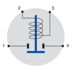
Let's imagine that your battery+ is attached to terminal #1 and your windlass+ is attached to terminal #4. We see that the windlass is not normally powered, because the switch is normally "open". For example, a spring may hold it in the "up" position shown in the picture.

Now, if we look at terminals #2 and #3 we see that they are two the two different sides of a coil -- an electromagnet. When that coil is energized, the electromagnet pushes the switch connection downward, connecting terminals #1 and #4. As long as that coil stays powered, the electromagnet is energized and the switch bar is pushed closed, supplying power to the windlass.

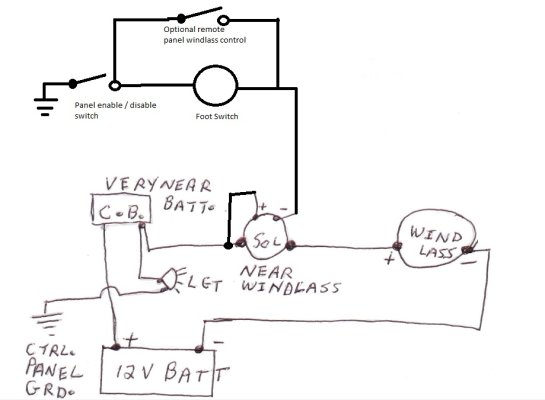
For this to work, we need to have +12V going into one end of the coil, and the other end of the coil connecting back to the 12v ground. So, the way this usually works is that +12V is supplied to one side of the coil, say terminal #2, and one wire of the foot switch is attached to the other side of the coil, say terminal #3. The other wire of the foot switch goes back to the 12 ground.

The foot switch is "normally open", meaning that it is an open connection until you step on it. So, while you aren't stepping on the foot switch, the coil isn't energized, and the switch controlling the windlass is open -- the windlass is off.

But, when you step on the foot switch, you close the switch, completing the circuit, allowing current to flow through the coil, energizing the electromagnet, and closing the switch that controls the windlass -- so the windlass is on as long as you are stepping on the foot switch and off otherwise.

This is done because it takes a relatively small amount of current to drive the electromagnet as compared to the windlass. This enables small wiring, etc, to the foot switch.

In /general/ 4-post (4 terminal) solenoids need a +12V supplied to each the coil and the load. In /general/ 3-post solenoids have a single +12V post (terminal) and split it internally so that it goes to each of the switch for the load and the input side of the coil.

Since you drew your solenoid with 4 posts (terminals), which is consistent with the figure for the terminal you showed, I think you need to supply +12V to each of the input side of the coil and to the input side of the load switch, even if by jumpering from one to the other.
 

Attachments

  • Diagram_H1_v2 jpg.jpg
    Diagram_H1_v2 jpg.jpg
    8.8 KB · Views: 264
I have added a suggested schematic with some notes.

Was this windlass installed aboard before? If so what was the wire size used originally? You can use that as a guide and maybe go up one size.

OR / ALso contact Ideal and ask how many amps or watts the motor draws. They may be able to tell or suggest to you what size C.B. to use to reduce guesswork.

I doubt the windlass needs a 150A C.B.

Cole Hersey I believe offers several different amp ratings greater than 85A continuous. Get one of those that is somewhat larger than the motor current, a 120A or a 200A. These are good relays BUT carry a spare.
 

Attachments

  • Windlass wiring sketch.pdf
    241.9 KB · Views: 42
more questions,
-I've got #2 wire for the high current, what size for the lower current circuits like the foot switch and small side of the solenoid?
-The motor is 45-50 amps with 65 amp surge, for a 50' circuit, ABYC says a #6 wire is big enough. That seems small? I was thinking #2. Thoughts?
Thanks
 
Last edited:
C Lectric posted a good schematic, but I'm curious why you want to switch the negative side with the solenoid. It's more common to switch the positive side. You just jumper from the + hot side of the solenoid to the + coil lead and then the foot switch runs to ground. This eliminates having to have two positive leads from the battery system that need protection. In C Letric's schematic, you'll also need a fuse for the control + wire that is fed to the foot switch in the 5-10 amp range.

BrianG, The Schafer schematic you posted a link to is switching the + side of the windlass and has the jumper shown to the solenoid positive with the foot switch controlling ground to the coil of the solenoid.
 
more questions,
-I've got #2 wire for the high current, what size for the lower current circuits like the foot switch and small side of the solenoid?
-The motor is 45-50 amps with 65 amp surge, for a 50' circuit, ABYC says a #6 wire is big enough. That seems small? I was thinking #2. Thoughts?
Thanks

Blue sea has a nice chart for sizing wire:

https://www.bluesea.com/resources/1437

For 50ft round trip and 70 amps, they recommend 4AWG. Your 2AWG will be fine, nothing wrong at all with oversize wire. The foot switch should be able to be powered with 16AWG, it's only 1-3 amps.
 
C Lectric posted a good schematic, but I'm curious why you want to switch the negative side with the solenoid. It's more common to switch the positive side. You just jumper from the + hot side of the solenoid to the + coil lead and then the foot switch runs to ground. This eliminates having to have two positive leads from the battery system that need protection. In C Letric's schematic, you'll also need a fuse for the control + wire that is fed to the foot switch in the 5-10 amp range.

BrianG, The Schafer schematic you posted a link to is switching the + side of the windlass and has the jumper shown to the solenoid positive with the foot switch controlling ground to the coil of the solenoid.
I am using C lectric's schematic though I am telling everyone I made it. Jk
 
C Lectric posted a good schematic, but I'm curious why you want to switch the negative side with the solenoid. It's more common to switch the positive side. You just jumper from the + hot side of the solenoid to the + coil lead and then the foot switch runs to ground. This eliminates having to have two positive leads from the battery system that need protection. In C Letric's schematic, you'll also need a fuse for the control + wire that is fed to the foot switch in the 5-10 amp range.

BrianG, The Schafer schematic you posted a link to is switching the + side of the windlass and has the jumper shown to the solenoid positive with the foot switch controlling ground to the coil of the solenoid.
not quite following you. I should modify C lectric's plan?
 
Well switching the negative/- makes things a bit more complicated and unusual so you might consider changing it. It will work as depicted but unless there's a good reason to do it that way, it will throw anyone else that needs to work on it for a loop.
 
If something can go just as well in the negative circuit then why not? Shunts for example, no need to have positive studs, terminals, and wires running to your dash/s when you can get the same reading off the negative side. The actual shunts are a huge spark target unless boxed over.
 
If something can go just as well in the negative circuit then why not? Shunts for example, no need to have positive studs, terminals, and wires running to your dash/s when you can get the same reading off the negative side. The actual shunts are a huge spark target unless boxed over.

In this case it adds extra need for fusing of the control wiring. Not saying it is wrong, just extra complication for no gain. Shunts are a different matter.
 
In this case it adds extra need for fusing of the control wiring. Not saying it is wrong, just extra complication for no gain. Shunts are a different matter.

Now I am 100% confused. I interpret C lectric's schematic as showing the solenoid jumping the + #2 wire. The #16 wired to theswitch also looks tied to the + with a negative grounded back to the windlass. the only other negative wires are the #2 wire from the battery post to the windlass itself and a ground for the idiot light.
 
BrianG you have it correct, I thought the solenoid was coming off the negative there. Sorry I misread that.

You could simplify further and jump the + to the solenoid and wire the foot switch to ground. Or you can add a fuse to the + that supplies the foot switch.
 
BrianG you have it correct, I thought the solenoid was coming off the negative there. Sorry I misread that.

You could simplify further and jump the + to the solenoid and wire the foot switch to ground. Or you can add a fuse to the + that supplies the foot switch.

Whew. I took half the boat apart yesterday and spent all day on my back routing the wires.
 
sorry clarify this por favor?

In C-Lectric's schematic, there is a wire that goes from (Panel 12V +) to a toggle switch, to the solenoid. This needs a fuse or circuit breaker, which is basically implicitly stated, but not depicted.

An alternative is to put a small gauge jumper from the (Solenoid +) to the battery side (ideally this would be a 20 gauge fusible link instead of plain wire) and then run the (Solenoid -) to your panel switch and then to ground. You could also put a remote panel windlass control which is helpful if you are needing to run the windlass while at the helm. I updated the schematic to show that idea.
 

Attachments

  • Windlass.jpg
    Windlass.jpg
    80.5 KB · Views: 15
Back
Top Bottom