Keith
I moved this from Welcome Mat to Maint & Systems - Power Systems to hopefully attract more responses.
Welcome aboard TF.
My $0.02
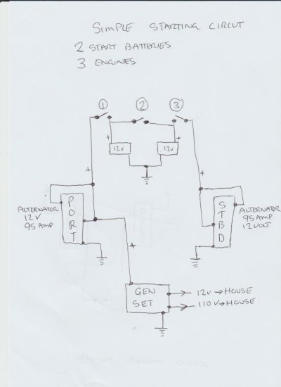
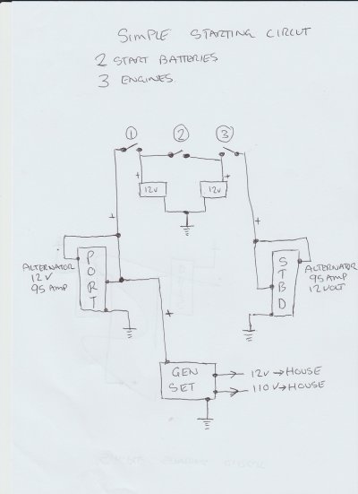
You don't show any solinoids (relays) to separate hi Amp circuit from low amp circuit which are used on essentially all starting circuits.
As a reference I'd suggest you take a look at Nigel Calders book "Boatowners Mechanical and Electrical Manual"
https://www.amazon.com/Boatowners-Mechanical-Electrical-Manual-4/dp/0071790330
It is a well regarded reference for boaters.
Be very cautious with modifying starting circuits as they are very high amp circuits, frequently not protected by fuses and can be hazardous if not installed safely.
Advice and an inspection by a marine electrician is advised if you are new / untrained in this area.